Dual-motor hybrid power drive system for rear drive

A technology of hybrid power and drive system, which is applied to the layout of multiple prime movers, power devices, and air pressure power devices of general power devices, and can solve the problems of limited fuel saving rate, large pollutant discharge, and fuel saving effect. no problem

Inactive Publication Date: 2021-06-08
CHONGQING TSINGSHAN IND
View PDF23 Cites 1 Cited by
  • Summary
  • Abstract
  • Description
  • Claims
  • Application Information

AI Technical Summary

Problems solved by technology

At present, most of the rear-drive longitudinal hybrid transmission technology schemes adopt the planetary row series-parallel scheme, or the single-gear series-parallel technical scheme, but the fuel saving rate of these two schemes is very limited, and the fuel saving effect is not good. , pollutant emissions are still relatively large

Method used


Image

  • Dual-motor hybrid power drive system for rear drive
  • Dual-motor hybrid power drive system for rear drive

Examples


Embodiment 1

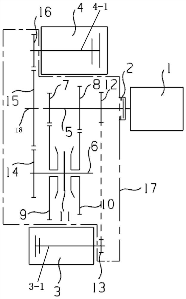
[0017] Example 1, as figure 1 As shown, when a synchronizer 11 is arranged between the first-speed driven gear 9 and the second-speed driven gear 10, the synchronizer 11 is circumferentially fixed on the intermediate shaft 6, the first-speed driving gear 7, the second-speed driving gear 8 are circumferentially fixed on the input shaft 5, the first-speed driven gear 9 and the second-speed driven gear 10 are clearance-fitted on the intermediate shaft 6, and the first-speed driven gear 9 and the second-speed driven gear 10 face each other. One end is respectively provided with engaging teeth, and the ring gear of the synchronizer 11 corresponds to the engaging teeth of the first-speed driven gear 9 and the second-speed driven gear 10 respectively, so that the synchronizer 11 is connected to the corresponding first-speed driven gear 9 or second-speed The driven gear 10 is engaged to complete the power transmission between the input shaft 5 and the intermediate shaft 6, and realize...

Embodiment 2

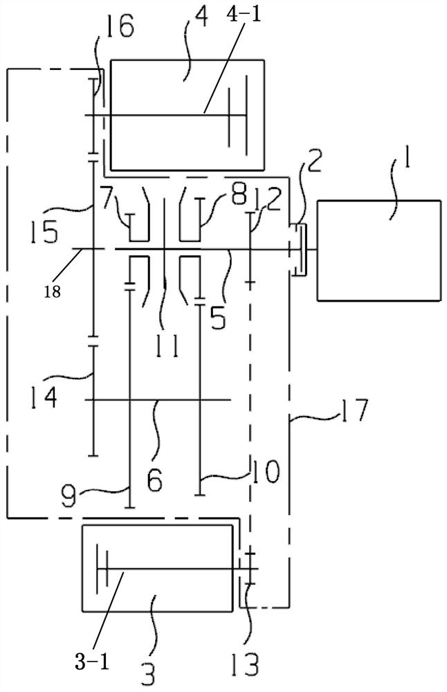
[0018] Example 2, as figure 2As shown, when a synchronizer 11 is arranged between the first-speed driving gear 7 and the second-speed driving gear 8, the synchronizer 11 is circumferentially fixed on the input shaft 5, and the first-speed driving gear 7 and the second-speed driving gear 8 are respectively The first-speed driven gear 9 and the second-speed driven gear 10 are respectively fixed on the intermediate shaft 6 in the circumferential direction, and the first-speed driving gear 7 and the second-speed driving gear 8 are respectively arranged at the opposite ends. Engagement teeth, the ring gear of the synchronizer 11 corresponds to the engaging teeth of the first-speed driving gear 7 and the second-speed driving gear 8 respectively, so that the synchronizer 11 is engaged with the corresponding first-speed driving gear 7 or the second-speed driving gear 8, and the completion is completed. The power transmission between the input shaft 5 and the intermediate shaft 6 real...


PUM


Abstract

A dual-motor hybrid power driving system for rear drive comprises an engine, a clutch and a transmission, the transmission comprises an input shaft, an intermediate shaft, an output shaft, a first motor shaft of a first motor and a second motor shaft of a second motor, and the input shaft is provided with a first-gear driving gear, a second-gear driving gear and a transmission gear. An output driving gear, a first-gear driven gear and a second-gear driven gear are sequentially arranged on the intermediate shaft, the first-gear driving gear is meshed with the first-gear driven gear, the second-gear driving gear is meshed with the second-gear driven gear, a first input gear is fixed to the first motor shaft in the circumferential direction, and a second input gear is fixed to the second motor shaft in the circumferential direction. The second input gear is meshed with the transmission gear, an output driven gear is fixed to the output shaft in the circumferential direction, and the output driven gear is meshed with the output driving gear and the first input gear. A synchronizer is arranged between the first-gear driving gear and the second-gear driving gear or between the first-gear driven gear and the second-gear driven gear, and the engine is connected with the input shaft through a clutch.

Description

technical field [0001] The invention relates to the technical field of automobile power transmission, in particular to a dual-motor hybrid drive system for rear drive. Background technique [0002] With the continuous consumption of non-renewable energy, the lack of energy and the national restrictions on vehicle exhaust emissions have seriously restricted the development of traditional fuel vehicles. There are also clear requirements for the fuel consumption of commercial vehicles. At present, most of the rear-drive longitudinal hybrid transmission technical solutions adopt the planetary series-parallel solution or the single-gear series-parallel technical solution, but the fuel-saving rate of these two solutions is very limited, and the fuel-saving effect is not good. , the pollutant emissions are still relatively large. SUMMARY OF THE INVENTION [0003] The purpose of the present invention is to aim at the deficiencies of the prior art, and to provide a dual-motor hyb...

Claims


Application Information

Patent Timeline
Patent Type & Authority Applications(China)
IPC IPC(8): B60K6/26B60K6/36B60K6/40B60K6/547
CPCB60K6/26B60K6/36B60K6/40B60K6/547
Inventor 蔺月萌罗会兵廖金龙严博王军民郭星左冰娥张裴
Owner CHONGQING TSINGSHAN IND
Why Eureka
Try Eureka