Multi-view pointer instrument identification method

A recognition method and pointer technology, applied in the field of image recognition, can solve the problems of difficult reading, slow manual reading, and manual reading cannot guarantee long-term monitoring, so as to solve the recognition problem and achieve the effect of improving the recognition effect.

Active Publication Date: 2018-11-06
ZHENGZHOU JINHUI COMP SYST ENG
View PDF10 Cites 25 Cited by
  • Summary
  • Abstract
  • Description
  • Claims
  • Application Information

AI Technical Summary

Problems solved by technology

However, manual reading has the following disadvantages: 1. The instrument is placed in a place where it is difficult for people to enter, and it is difficult to read; 2. Manual reading cannot guarantee long-term monitoring; 3. The visual fatigue of the operator is prone to reading errors; 4. Manual reading fetch speed is slow
[0006] Most of the above methods are aimed at instruments with large dial area, clear dial image, short shooting distance or frontal shooting, which have better recognition effect. For the problem of multi-view angles such as side view and upward view, it is impossible to accurately read the instrument. Indicates the number

Method used


Image

  • Multi-view pointer instrument identification method
  • Multi-view pointer instrument identification method
  • Multi-view pointer instrument identification method

Examples


Embodiment 1

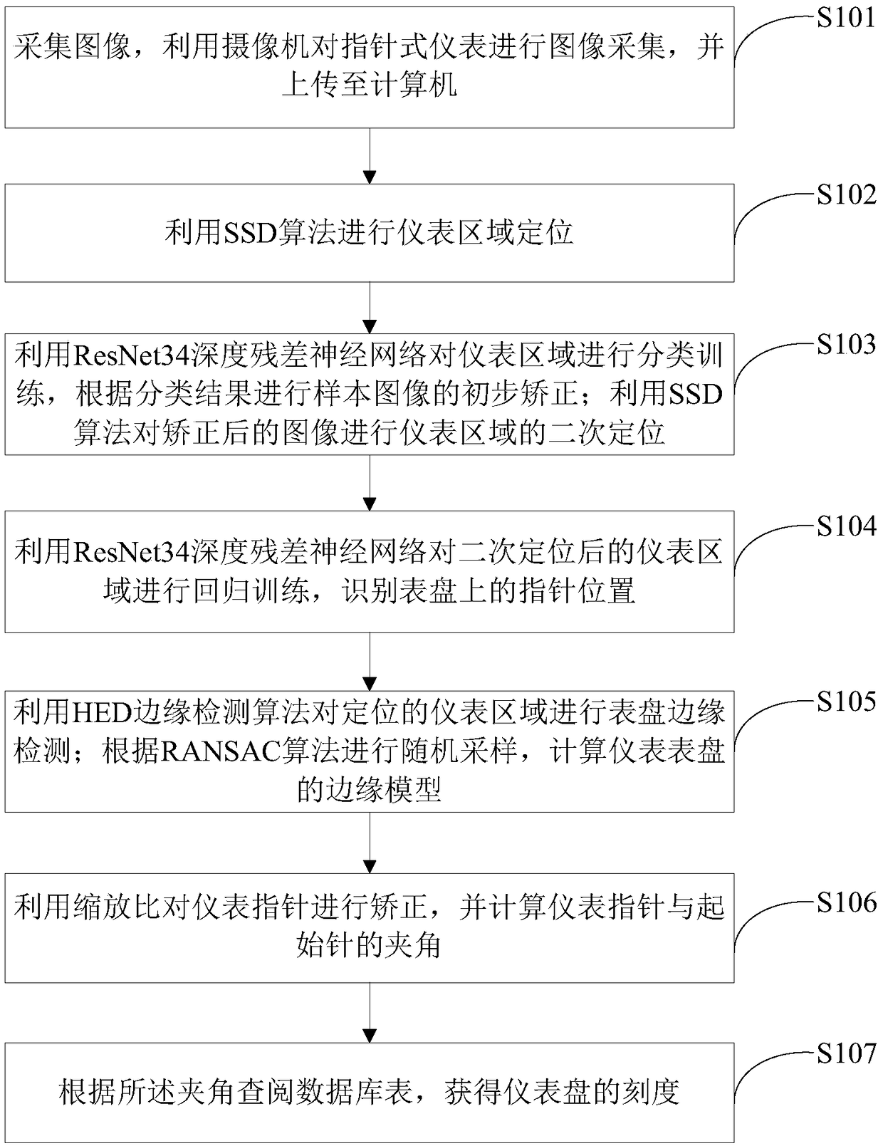
[0067] Such as figure 1 As shown, a multi-view pointer instrument recognition method of the present invention comprises the following steps:

[0068] Step S101: collecting images, using a camera to collect images of pointer instruments, and uploading them to a computer;

[0069] Step S102: use the SSD algorithm to locate the meter area;

[0070] Step S103: Use the ResNet34 deep residual neural network to perform classification training on the instrument area, and perform preliminary correction of the sample image according to the classification result; use the SSD algorithm to perform secondary positioning of the instrument area on the corrected image;

[0071] Step S104: use the ResNet34 deep residual neural network to perform regression training on the instrument area after the secondary positioning, and identify the position of the pointer on the dial;

[0072] Step S105: Use the HED edge detection algorithm to detect the dial edge of the positioned instrument area; perfo...

Embodiment 2

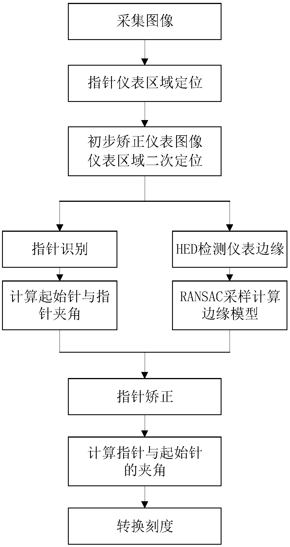
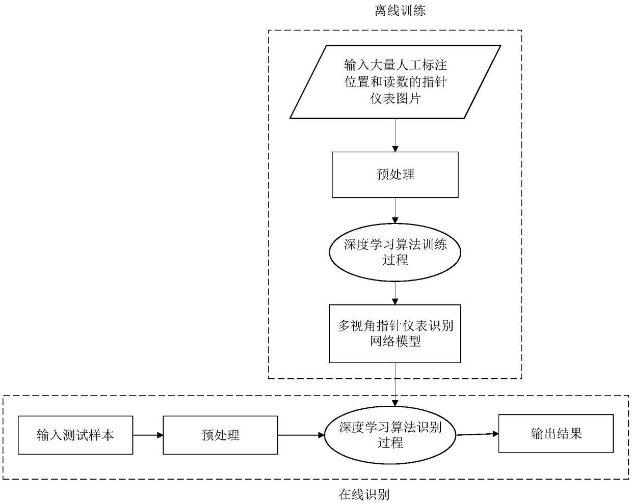
[0076] Such as figure 2 , image 3 As shown, another multi-view pointer instrument recognition method of the present invention includes the following steps:

[0077] Step 1: Collect images, use the camera to collect images of pointer instruments, and upload them to the computer.

[0078] Step 2: Position the pointer instrument area.

[0079] The SSD algorithm is used to locate the meter area for the collected sample data, Figure 4 Locate the block diagram for the gauge area.

[0080] The specific implementation process is as follows:

[0081] 1) Preprocess the sample data to obtain sample data with a size of 300×300×3.

[0082] 2) Construct the SSD network model. On the basic network structure of VGG16, the fully connected layers of the 6th and 7th layers are converted into convolutional layers, and the feature map sizes are 38×38 and 19×19. Then add 3 convolutional layers and an average pooling layer, that is, the average pool layer, and the feature map sizes are 10×1...


PUM


Abstract

The present invention relates to the technical field of image recognition. A multi-view pointer instrument identification method includes: acquiring an image and uploading the image to a computer; using a SSD algorithm to position an instrument area; using a ResNet34 deep residual neural network to perform classification training on the instrument area, and performing preliminary correction on thesample image according to a classification result; using the SSD algorithm to secondarily position the instrument area of the corrected image; using the network to perform regression training on thesecondarily positioned instrument area to identify the position of a pointer on an instrument dial; using an HED edge detection algorithm to perform dial edge detection on the positioned instrument area; performing random sampling according to an RANSAC algorithm, and calculating the edge model of the instrument dial; correcting the instrument point by a zoom ratio, and calculating the angle between the instrument point and a start point; and looking up a database to obtain the scales of the instrument dial. The method can recognize the pointer instrument captured at different angles.

Description

technical field [0001] The invention relates to the technical field of image recognition, in particular to a multi-view pointer instrument recognition method. Background technique [0002] At present, most of the readings of pointer instruments are carried out manually. However, manual reading has the following disadvantages: 1. The instrument is placed in a place where it is difficult for people to enter, and it is difficult to read; 2. Manual reading cannot guarantee long-term monitoring; 3. The visual fatigue of the operator is prone to reading errors; 4. Manual reading Fetching is slow. [0003] Although using machine vision technology instead of human eyes to identify pointer instruments can minimize the influence of human factors, increase the speed of instrument reading, and reduce the labor intensity of workers. However, the few existing meter reading methods based on machine vision can achieve better reading results under ideal conditions, but in practical applica...

Claims


Application Information

Patent Timeline
Patent Type & Authority Applications(China)
IPC IPC(8): G06K9/46G06K9/62G06N3/04
CPCG06V10/44G06N3/045G06F18/214
Inventor 张晨民彭天强李丙涛
Owner ZHENGZHOU JINHUI COMP SYST ENG
Why Eureka
Try Eureka