
Railway mobile power generation equipment

A mobile power generation and equipment technology, applied in the direction of electromechanical devices, electrical components, mechanical equipment, etc., can solve the problems of potential safety hazards, easy to exceed the container-type power generation box, and can not be exceeded, so as to reduce the occupied space and increase the total air inlet. area, effect of lowering the center of gravity

Pending Publication Date: 2018-11-06
CRRC YANGTZE CO LTD
View PDF0 Cites 4 Cited by
  • Summary
  • Abstract
  • Description
  • Claims
  • Application Information

AI Technical Summary

Problems solved by technology

Moreover, due to the limited requirements of the container-type generator box, all components installed on the container-type generator box cannot exceed the corner fittings of the container-type generator box. the boundaries
[0006] At the same time, ordinary container refueling windows are all outward-opening refueling windows, and operators operate from the outside of the container, while railway containers have very strict requirements on the limit because they run on the railway, and the outward-opening refueling windows must exceed the railway limit when they are opened. There is a very big security risk
In addition, the outward-opening refueling window is generally installed at the side end, and when opened, it exceeds the limit of the corner fittings, so it is easy to cause safety hazards during railway operation

Method used


Image

  • Railway mobile power generation equipment
  • Railway mobile power generation equipment
  • Railway mobile power generation equipment

Examples


Embodiment Construction

[0065] The present invention will be further described in detail below in conjunction with the accompanying drawings and specific embodiments.

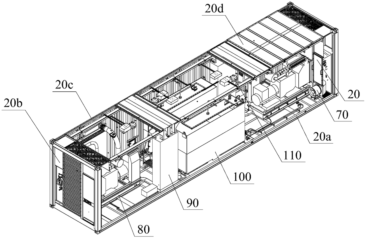
[0066] Such as figure 1 Shown is railway mobile power generation equipment, including a box body 20, and two sets of diesel generator sets 80, a fuel oil device 100, a fire protection system 110, an electrical device 90 and two sets of exhaust devices 70 built in the cavity of the box body 20; Wherein, the box body 20 includes a box bottom frame component 20a, two end wall components 20b, two side wall components 20c and an upper cover 20d.

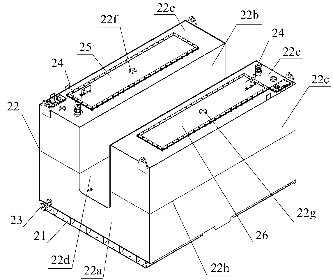
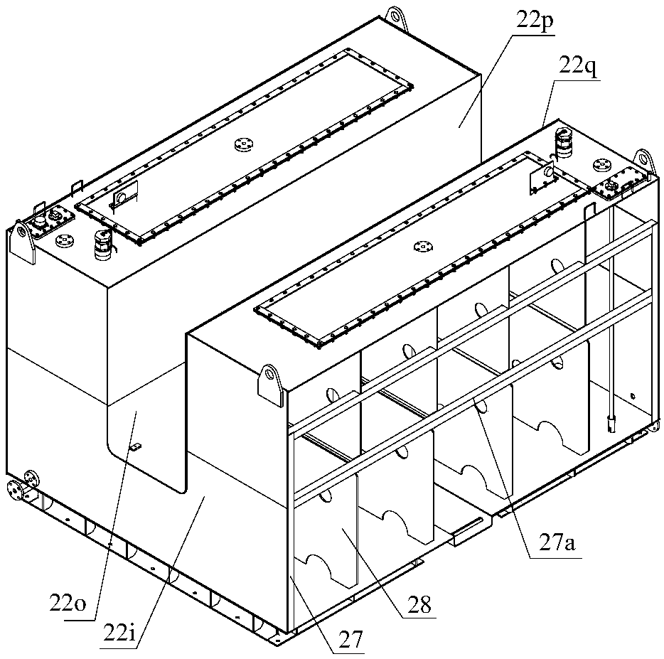
[0067] combine figure 2 The section of the fuel tank 22 fixed on the bottom plate 21 of the tank chassis 20a by bolts is U-shaped in section, and its fuel tank 22 includes a bottom fuel tank 22a, a left fuel tank 22b that is arranged on the left side of the top surface of the bottom fuel tank 22a and communicates with the bottom fuel tank 22a And the right side fuel tank 22c that is arranged o...


PUM


Abstract

The invention discloses railway mobile power generation equipment. The equipment comprises a box body and two sets of diesel generator, a fuel device, a fire-fighting system, an electrical device andtwo sets of air exhausting device that are all arranged in a cavity of the box body, wherein the box body comprises a box bottom rack assembly, end wall assemblies at two ends, side wall assemblies attwo sides, and an upper cover, a section of an oil tank fixed on a bottom board of the box bottom rack assembly is of a U-shaped structure, the oil tank comprises a bottom oil tank, a left oil tank arranged at the left of the top of the bottom oil tank and communicated with the bottom oil tank, and a right oil tank arranged at the right of the top of the bottom oil tank and communicated with thebottom oil tank, and the inner vertical surface of the left oil tank, the inner vertical surface of the right oil tank and the top surface of the bottom oil tank enclose to form a U shaped cavity. Fewer oil tanks are used, and pipelines between the oil tanks are reduced correspondingly, so that the oil tank has a compact structure, the oil tanks occupy a smaller space, and the space of the mobilepower generation equipment can be fully utilized. The overall height of the oil tank is reduced, so that the center of gravity of the oil tank is lowered, and the oil tank is more stable.

Description

technical field [0001] The invention belongs to the technical field of power generation equipment, and in particular relates to a railway mobile power generation equipment. Background technique [0002] There are many types of containers, which can be divided into general-purpose containers, ventilated boxes, dry bulk containers, insulated boxes, heat-insulated boxes, platform boxes, tank boxes, and special boxes according to their uses. The power box is a kind of special container. Generally, a generator set is placed in the box, and the engine of the generator set uses diesel or natural gas as fuel. There is a sound insulation and noise reduction layer inside the box, and the noise emission index of the generator set should meet the corresponding national standards. [0003] The diesel generator set arranged in the car outputs power to the outside, and the fuel tank provided with the car provides fuel for the unit. Since the railway mobile power generation equipment is u...

Claims


Application Information

Patent Timeline
Patent Type & Authority Applications(China)
IPC IPC(8): H02K5/04H02K5/20H02K5/10H02K5/24H02K9/14
CPCH02K5/04H02K5/10H02K5/20H02K5/24H02K9/14H02K7/1815H02K5/207F02B63/044
Inventor 舒麟高建华景传峰何远新刘凤伟胡海滨马鹏超金晓平孙纯旭张敏黄圣罗桂琼夏明谢斌吴东施振昌
Owner CRRC YANGTZE CO LTD
Learn More