
An intelligent rotating anti-myopia TV and an anti-myopia method

An anti-myopia and TV technology, which is applied in the field of TV, can solve the problems of large detection blind spot, too close to the TV screen, and the inability to detect people watching TV obliquely, etc., achieves strong anti-interference performance, improves sound playback effect, and The effect of small detection blind spots

Active Publication Date: 2020-12-22
TRULY OPTO ELECTRONICS
View PDF6 Cites 0 Cited by
  • Summary
  • Abstract
  • Description
  • Claims
  • Application Information

AI Technical Summary

Problems solved by technology

[0004] The purpose of the present invention is to provide an intelligent rotating anti-myopia TV and an anti-myopia method to solve the problem that the existing anti-myopia TV has a relatively large detection blind spot and cannot detect whether people watching TV obliquely are too close to the TV screen

Method used


Image

  • An intelligent rotating anti-myopia TV and an anti-myopia method
  • An intelligent rotating anti-myopia TV and an anti-myopia method
  • An intelligent rotating anti-myopia TV and an anti-myopia method

Examples


Embodiment 1

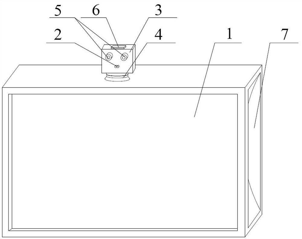
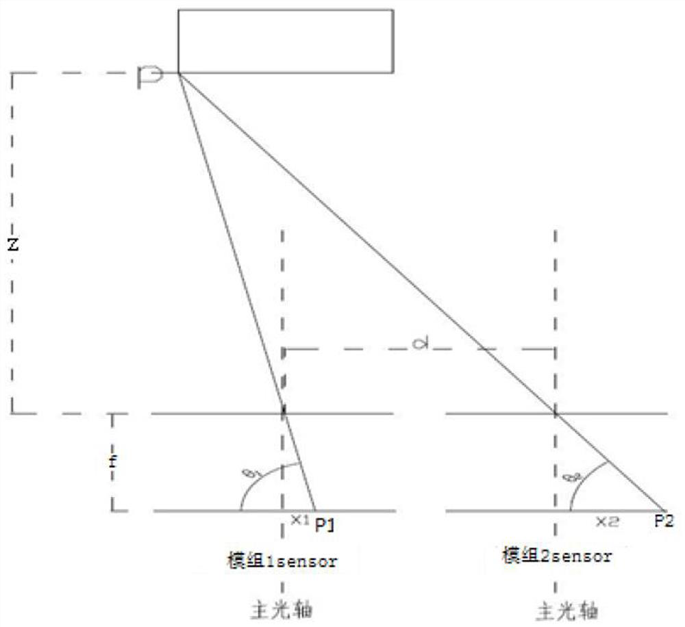
[0041] like Figure 1~2As shown, an intelligent rotating anti-myopia TV set of the present invention includes a TV body 1 and an infrared detector 2. The infrared detector 2 is used to sense infrared signals of the human body and is connected to the power switch of the TV body 1 through wires. Including a detection panel 3, the bottom end of the detection panel 3 is connected to the top of the TV body 1 through an electric rotating column 4, and a distance-measuring dual camera 5 is arranged on the board surface of the detection panel 3, and the distance-measuring dual camera 5 is connected to the television The power switch of the body 1 is connected by wires; the infrared detector 2 is installed on the detection panel 3, and the detection surface of the infrared detector 2 is located in the same direction as the detection surface of the ranging dual camera 5, and the infrared detector 2 and the motorized The rotating column 4 is connected by a wire, and when the infrared det...

Embodiment 2

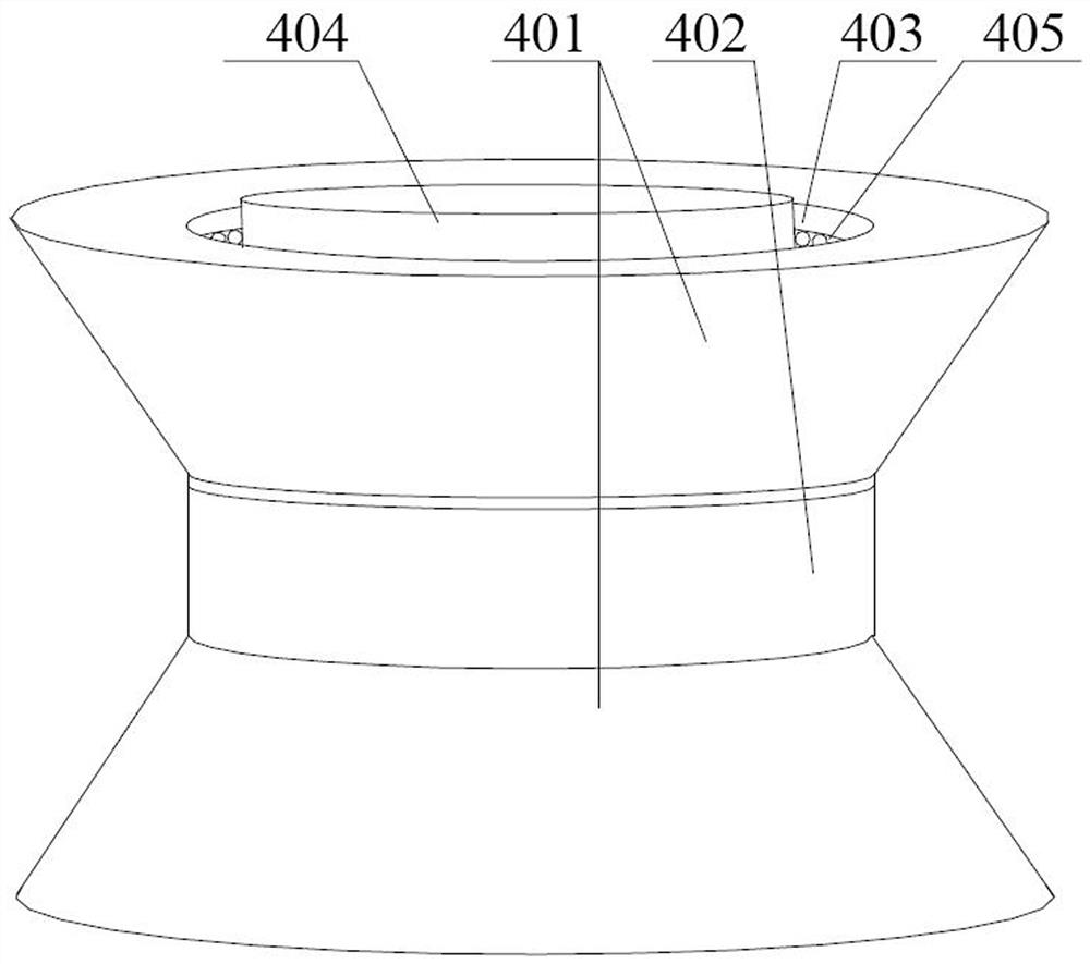
[0058] like Figure 3~4 As shown, on the basis of Embodiment 1, the electric rotating column 4 includes two circular platforms 401 and a cylindrical connecting cylinder 402, and the end faces of the circular platforms 401 with smaller diameters are connected to the end surfaces of the cylindrical connecting cylinder 402. The end faces of each round platform 401 are all provided with a through hole 403, and the through hole 403 communicates with the cylindrical connection cylinder 402, and also includes a motor controller, a motor and a rotating shaft 404, and the motor controller and the motor are all installed on the TV body. 1, the output shaft of the motor is fixed to one end of the rotating shaft 404, and the other end of the rotating shaft 404 is fixed to the bottom end of the detection panel 3. A bearing 405 is embedded in the inner wall of the through hole 403 , and the centerline of the bearing 405 coincides with the centerline of the through hole 403 . The electric r...

Embodiment 3

[0060] like Figure 5 As shown, there is also a groove 7 on both sides of the TV body 1, the inner wall of the groove 7 is an arc surface, and the diameter of the groove 7 decreases along its axial direction towards the bottom end surface of the groove 7, There are several sound-enhancing holes 8 on the side inner wall of the groove 7 . The bottom surface of the groove 7 is covered with a copper film 9 . In the present invention, grooves 7 are provided on both sides of the TV body 1, and the inner wall of the groove 7 is an arc surface, so that the whole groove 7 becomes a horn housing structure, which can facilitate the gathering of sound, form reverberation, and improve the sound of the TV. Playback effect.


PUM


Abstract

The invention discloses a smart rotating anti-myopia television and an anti-myopia method, which comprises a television body and an infrared detector, wherein the infrared detector is used for sensingan infrared signal of a human body and is connected with a power switch of the television body through a wire; the smart rotating anti-myopia television further comprises a detecting panel, wherein the bottom end of the detecting panel is connected with the top end of the television body through an electric rotating column; a distance measuring double-camera is arranged on the surface of the detecting panel, and the distance measuring double-camera is connected with the power switch of the television body through a wire; the infrared detector is installed on the detecting panel, and the detecting surface of the infrared detector and the detecting surface of the distance measuring double-camera are located in the same direction; and the infrared detector is connected with the electric rotating column through a wire. The smart rotating anti-myopia television and the anti-myopia method in the invention solve the problem that the detection blind area of the existing anti-myopia televisionis large, and the problem cannot be detected whether the person who obliquely watches the television is too close to the television screen.

Description

technical field [0001] The invention relates to a TV set, in particular to an intelligent rotating anti-myopia TV set and a method for preventing myopia. Background technique [0002] With the improvement of living standards, TV sets are one of the necessary electrical appliances in every household. At the same time, the size of TV sets is getting bigger and bigger. Many primary school students have myopia early on due to improper viewing. In order to solve the above-mentioned technical problems, many anti-myopia TV sets have occurred in the prior art, and this TV set is provided with an infrared detector, and the infrared detector is connected with the opening and closing circuit of the TV power supply. The TV anti-myopia automatic alarm can set the distance. When the infrared detector detects that someone is approaching through infrared rays, it will send an alarm to remind people to keep a certain distance when watching TV. If it is serious, it will control the power of t...

Claims


Application Information

Patent Timeline
Patent Type & Authority Patents(China)
IPC IPC(8): H04N21/442H04N21/41H04N5/64H04N5/60
CPCH04N5/607H04N5/64H04N21/4122H04N21/44218
Inventor 吴光斯杜映丹李航陈城荣
Owner TRULY OPTO ELECTRONICS
Learn More