Food producing equipment

A kind of equipment and food technology, applied in kitchen utensils, home utensils, roasters/barbecue grids, etc., can solve problems such as poor texture, waste of heat, affecting food taste, etc., and achieve the effect of enhancing comprehensive performance and reducing temperature

Pending Publication Date: 2018-11-09
FOSHAN SHUNDE KUFU ELECTRIC APPLIANCES CO LTD
View PDF10 Cites 13 Cited by
  • Summary
  • Abstract
  • Description
  • Claims
  • Application Information

AI Technical Summary

Problems solved by technology

In the above technical solution, the cold wind wheel is arranged above the motor, specifically between the motor and the air inlet hole, and the cold wind introduced by the wind-inducing wind wheel from the outside of the casing mainly acts between the casing and the food cavity, and transfers the food cavity to the food cavity. The heat from the casing part is driven downwards and discharged through the air outlet at the bottom. The disadvantage of this arrangement is that the cold wind introduced into the casing by the cold wind wheel does not directly act on the motor, and the heat generated by the motor is accumulated, resulting in The temperature of the motor itself is too high, which will damage the motor; moreover, the cold air directly acts on the outer wall of the cavity, and directly discharges the heat transferred from the cavity to the outer wall. Although it solves the problem of residual harmful heat, it will take away more The useful heat, the temperature difference between the inside and outside of the cavity is too high, causing part of the useful heat to be directly transferred to the outer wall of the cavity, and then taken out, resulting in waste of heat, which in turn increases the cooking time of food. With the increase of cooking time, it will affect The taste of food, especially food such as potato cubes, will lead to softness and poor texture when heated for a long time

Method used


Image

  • Food producing equipment
  • Food producing equipment
  • Food producing equipment

Examples


Embodiment 1

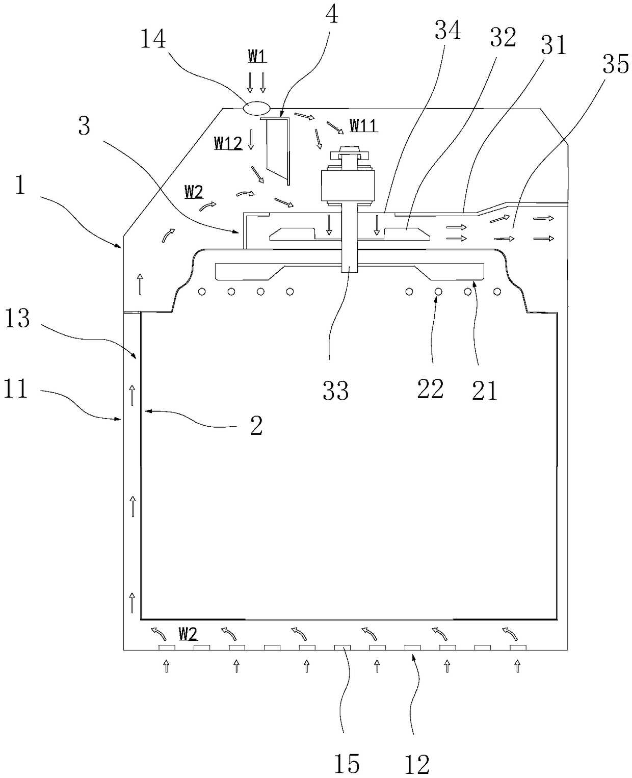
[0043] This embodiment provides a device for making food, such as figure 1 As shown, it specifically includes a housing 1 , a food preparation chamber 2 , an air induction device 3 and a guide device 4 .

[0044] Wherein, the food preparation chamber 2 is located inside the casing 1, and the air blast wheel 21 and the electric heating tube 22 are arranged inside the food preparation room 2, and the electric heating pipe 22 is arranged directly below the air blast wheel 21, and the air blower The wind wheel 21 is used to generate the flowing air flow, and the electric heating tube 22 is used to heat the air flow generated by the blower wind wheel 21 to form a high-temperature air flow; the high-temperature air flow circulates inside the food production chamber 2 and continuously flows from the surface of the food. To complete the heating process of food.

[0045] The draft device 3 comprises a draft cover 31, a draft wind wheel 32 and a motor 33, the draft cover 31 is located ...

Embodiment 2

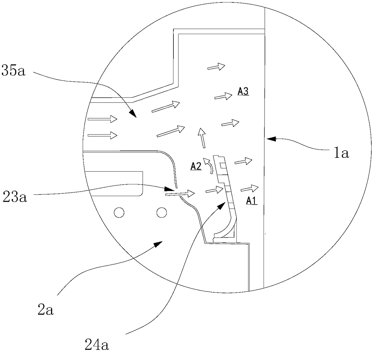
[0051] The difference between this embodiment and Embodiment 1 is that on the basis of Embodiment 1, the airflow for cooling the motor is reused, specifically as figure 2 As shown, the food preparation chamber 2a is provided with a water vapor outlet 23a, and the water vapor outlet 23a is located below the air outlet 35a; the water vapor outlet 23a is provided with a flow mixer 24a, and the flow mixer 24a forces part of the high-temperature gas discharged from the water vapor outlet 23a to The cooling air flows discharged from the air discharge port 35a are mixed.

[0052] The structure of the flow mixer 24a in this embodiment includes a splitter plate arranged inwardly along the water vapor outlet 23a, and a plurality of small holes are arranged on the splitter plate, and a part (a small amount) of the gas discharged from the water vapor outlet 23a directly passes through the above-mentioned Small orifice discharge, such as figure 2 As shown by the arrow A1 in the figure, ...

Embodiment 3

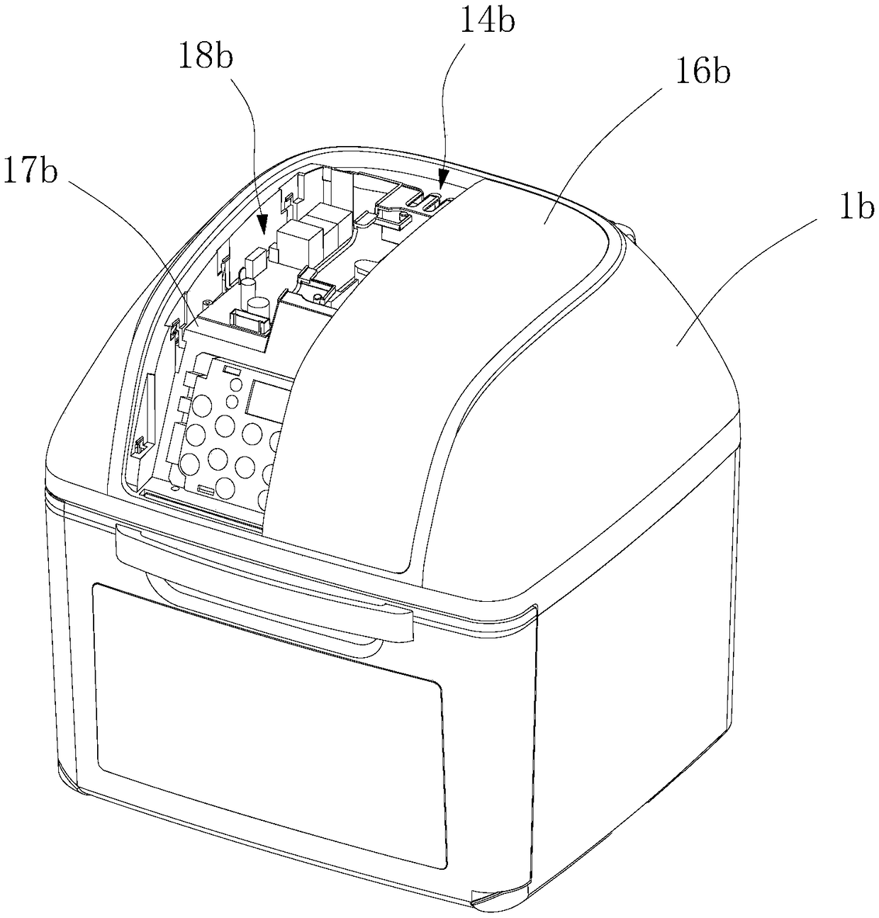
[0055] The difference between this embodiment and embodiment 1 is that, as image 3 As shown, an upper cover 16b is provided on the top of the housing 1b, and the housing 1b is provided with a plurality of heat insulation boards 17b extending inwardly along the inner side wall of the upper cover 16b, wherein the heat insulation boards 17b are fixed on the housing On 1b, the upper cover 16b is buckled on the top of the heat insulation board 17b, and forms a heat insulation space 18b enclosed between the heat insulation board 17b. The heat insulation space 18b is used to place electronic devices, such as control circuit boards and electronic buttons, etc. It communicates with the upper air vent 14b; part of the main cooling air flow passes through the upper air inlet 14b and flows into the heat insulation space 18b to form the third cooling branch flow; wherein, the third cooling branch flow is mainly to make cold air enter the heat insulation space. In the space 18b, the heat g...


PUM


Abstract

The invention provides food producing equipment. The equipment comprises a casing, a food producing chamber arranged in the casing and an air inducing device arranged on the outer side of the upper side of the food producing chamber, wherein the air inducing device comprises an air inducing hood and an air inducing device, an air inducing port is formed in the top of the air inducing cover, and the air inducing device forces air to penetrate through the air inducing port to flow into the air inducing hood; an upper air inlet is arranged at the top of the casing, and air flows into the casing from the upper air inlet and penetrates through the air inducing port to flow into the air inducing hood to form main cooling airflow; the casing comprises side walls and a bottom wall, and an interlayer is arranged between each side wall and the food producing chamber; a lower air inlet is arranged on the bottom wall, and air flows into the interlayer from the lower air inlet, flows upwards slowlyalong the interlayer and penetrates through the air inducing port to flow into the air inducing hood to form auxiliary cooling airflow. The equipment can effectively discharge harmful heat in the casing and reduces the discharge rate of heat in the food producing chamber.

Description

technical field [0001] The invention belongs to the field of household appliances, and in particular relates to a device for making food. Background technique [0002] In the process of using high-temperature air flow to make food, the high-temperature air flow carries a large amount of heat, and through contact with the surface of the food, the heat is transferred to the food to complete the cooking of the food; however, during the process of circulating the high-temperature air flow in the food preparation chamber , It will also increase the temperature of the outer wall around the food preparation room. As time goes by, the outer wall will transfer part of the heat to the shell, causing the shell to heat up. At this time, the heat transferred to this part of the shell needs to be discharged. [0003] On the other hand, the generation of high-temperature air flow is based on electrical components, such as motors. There are also electronic components such as control circuit...

Claims


Application Information

Patent Timeline
Patent Type & Authority Applications(China)
IPC IPC(8): A47J37/06
CPCA47J37/0629A47J37/0641A47J37/0664
Inventor 程晓梁福林肖丙三
Owner FOSHAN SHUNDE KUFU ELECTRIC APPLIANCES CO LTD
Why Eureka
Try Eureka