Machining device of hydraulic oil cylinder welding part cylinder bottom and machining method thereof

The invention relates to a processing device and a technology for a hydraulic cylinder, which is applied to the field of processing devices for the cylinder bottom of a hydraulic cylinder welding piece, and can solve the problems of poor verticality and symmetry of earring sleeves, inconsistent processing benchmarks, unstable positioning, etc., and achieves improved processing efficiency, The effect of improved processing consistency and reasonable structure

Pending Publication Date: 2018-11-09
BENGBU YELI MACHINERY
View PDF6 Cites 0 Cited by
  • Summary
  • Abstract
  • Description
  • Claims
  • Application Information

AI Technical Summary

Problems solved by technology

[0005] The purpose of the present invention is to overcome the deficiencies of the prior art, and provide a processing device and processing method for the cylinder bottom of a hydraulic cylinder weldment, so as to solve the problem of earrings caused by non-uniform processing standards, welding deformation and unstable positioning in the prior art. The problem of the verticality and symmetry of the sleeve relative to the cylinder bottom is poor, and the processing quality of the cylinder bottom weldment is improved.

Method used


Image

  • Machining device of hydraulic oil cylinder welding part cylinder bottom and machining method thereof
  • Machining device of hydraulic oil cylinder welding part cylinder bottom and machining method thereof
  • Machining device of hydraulic oil cylinder welding part cylinder bottom and machining method thereof

Examples


Embodiment Construction

[0021] Below in conjunction with embodiment and accompanying drawing thereof, the present invention is described in further detail:

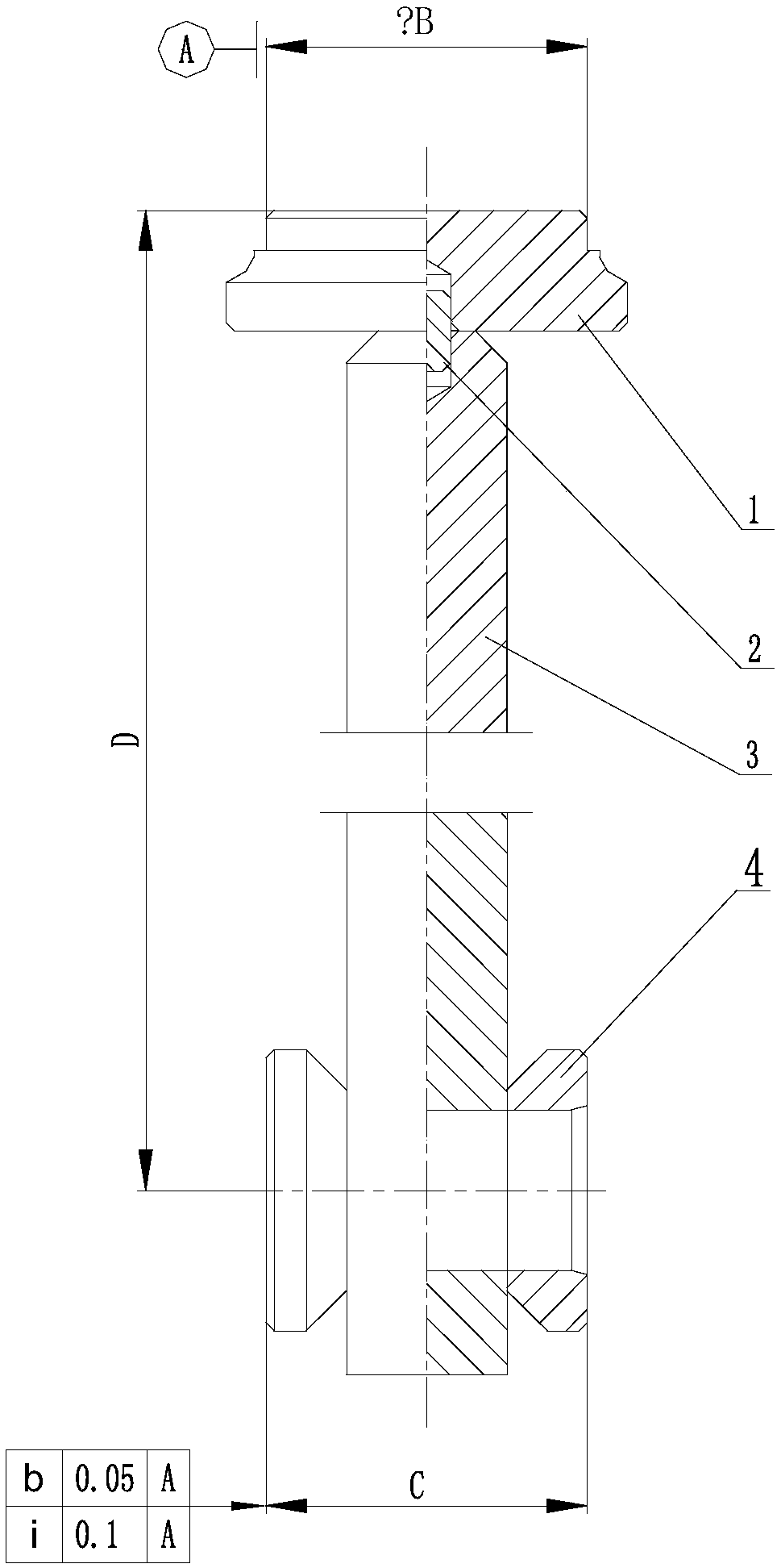
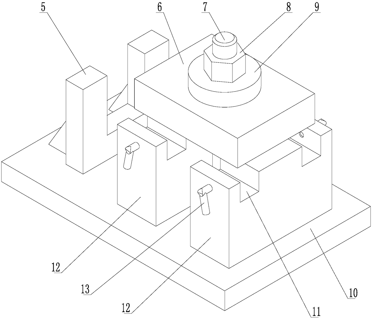
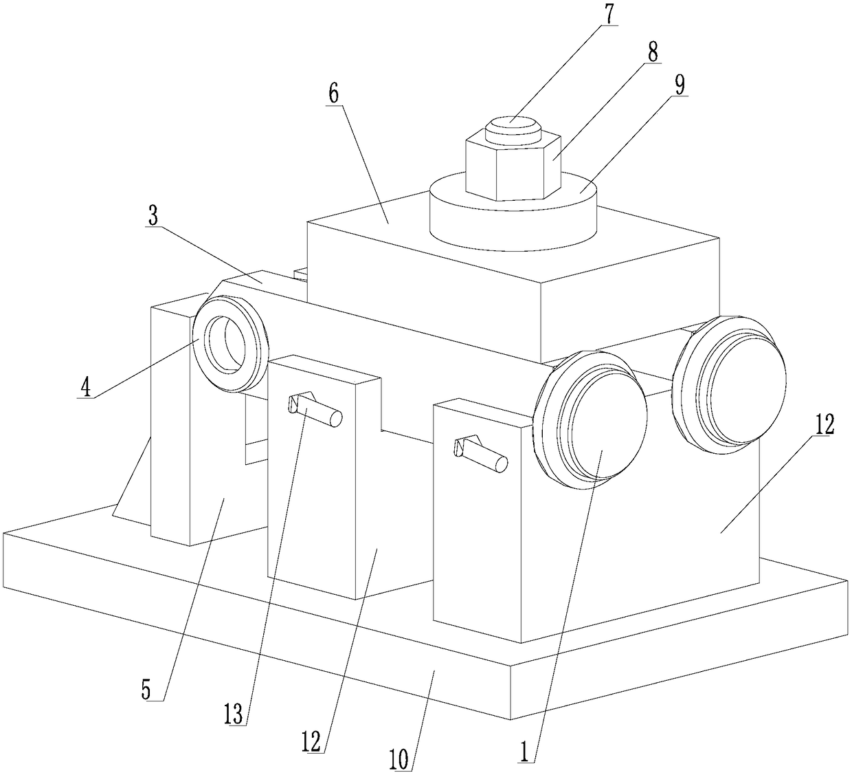
[0022] see Figure 1 to Figure 3 , a processing device for the cylinder bottom of a hydraulic cylinder weldment, comprising a limit block 5, a pressure plate 6, a stud 7, a nut 8, a spacer 9, a bottom plate 10, a positioning block 12 and a top wire 13, and the bottom plate 10 is provided with There are two sets of positioning blocks 12, each set of positioning blocks 12 is provided with two symmetrical positioning grooves 11, the earrings 3 are placed in the positioning grooves 11, the outer surface of the positioning grooves 11 is provided with a top wire 13, and the top wire 13 tightens the earrings 3 In the positioning groove 11; the bottom 10 is provided with a bolt 7, and after the cushion block 9 and the pressing plate 6 pass through the bolt 7, they are pressed by the nut 8 to fix the earring 3 in the positioning groove 11; the bottom pla...


PUM


Abstract

The invention relates to a machining device of a hydraulic oil cylinder welding part cylinder bottom and a machining method thereof. The machining device of the hydraulic oil cylinder welding part cylinder bottom comprises a limiting block, a pressing plate, a double-screw bolt, a nut, a cushion block, a positioning block, a bottom plate and a jack screw. The positioning block is arranged on the bottom plate. A positioning groove is formed in the positioning block. The welding part cylinder bottom is placed in the positioning groove, the jack screw is arranged on the side surface of the positioning groove, and the jack screw ejects the welding part cylinder bottom into the positioning groove. The bottom plate is provided with a bolt, the cushion block and the pressing plate are pressed bythe nut after passing through the bolt, and the welding piece cylinder bottom is fixed into the positioning groove. The bottom plate is provided with the limiting block, the limiting block correspondsto one end of the positioning groove, and the end portion of a workpiece placed in the positioning groove is attached to the limit block and positioned. According to the machining method of the hydraulic oil cylinder welding part cylinder bottom, the machining device is used for carrying out welding, end face milling and drilling hole and reaming machining on the welding part cylinder bottom. Themachining device of the hydraulic oil cylinder welding part cylinder bottom has a reasonable structure, the machining efficiency is improved, form and position tolerance is ensured, processing reliability is improved, and the cost is low, and machining device of the hydraulic oil cylinder welding part cylinder bottom is easy to manufacture.

Description

technical field [0001] The invention relates to a processing method of a hydraulic oil cylinder part, in particular to a processing device and a processing method for a cylinder bottom of a welded part of a hydraulic oil cylinder. Background technique [0002] The cylinder bottom is one of the components of the hydraulic cylinder, which mainly plays the role of connecting with the external mechanism. Welded part cylinder bottom is composed of cylinder bottom, cylindrical pin, earring and earring sleeve. The general processing method of welded cylinder bottom is to process the cylinder bottom and earring first, then weld the cylinder bottom and earring sleeve to the earring respectively, and finally use The end surface of the cylinder bottom is the processing standard for processing earrings. [0003] In this processing method, the welding of the cylinder bottom and the earrings is based on the earrings, and the processing of the earrings is based on the end face of the cyli...

Claims


Application Information

Patent Timeline
IPC IPC(8): B23P23/04B23Q3/06B23Q15/00
CPCB23P23/04B23Q3/062B23Q15/00
Inventor 孙鸿钧易新新鄢超宋晓洁王鹏飞阮晓东叶李军
Owner BENGBU YELI MACHINERY
Why Eureka
Try Eureka