Unmanned carrying trolley

A technology for transporting trolleys and car bodies, which is applied to lifting devices, lifting frames, etc., can solve the problems of trolley derailment, skidding, accidents, etc., and achieves the effect of compact structure, stable lifting process and small space occupation.

Pending Publication Date: 2018-11-09
SHENZHEN JINGZHI HI TECH ROBOT CO LTD
View PDF16 Cites 7 Cited by
  • Summary
  • Abstract
  • Description
  • Claims
  • Application Information

AI Technical Summary

Problems solved by technology

When the load of the unmanned trolley is light, this structure can play a good role in stabilizing; but when the load of the unmanned trolley is heavy, it is easy to slip, causing the trolley to derail or cause an accident

Method used


Image

  • Unmanned carrying trolley
  • Unmanned carrying trolley
  • Unmanned carrying trolley

Examples


Embodiment 1

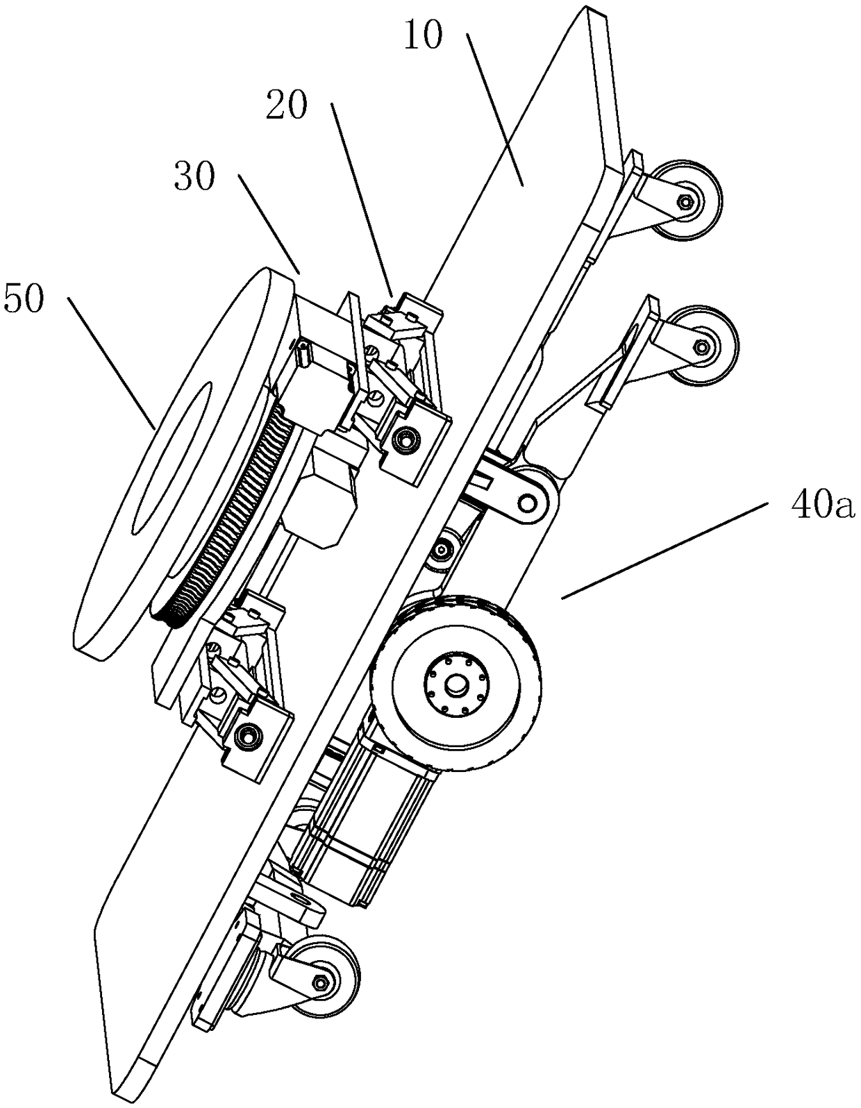
[0035] Such as Figure 1 to Figure 8 As shown, an unmanned transport trolley includes a body 10 , two jacking mechanisms 20 arranged parallel to the upper end of the body 10 , and a driving mechanism 40 a arranged at the bottom of the body 10 .

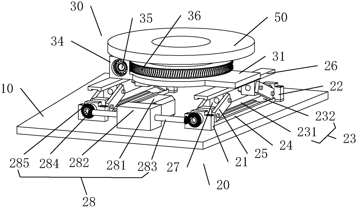
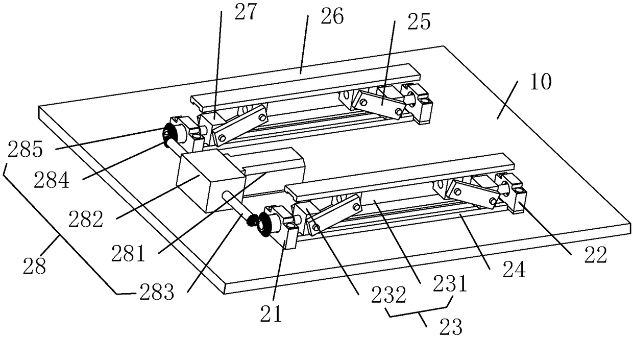
[0036] Specifically, the jacking mechanism 20 includes a fixed base 21 fixed on the installation base 10, a support base 22 fixed on the installation base 10 and opposite to the fixed base 21, and the two ends are respectively rotated on the fixed base 21 and the support base 22. The double-ended screw 23 , the power structure 28 for driving the screw 231 to rotate, and the slide rail 24 fixed on the installation base 10 and located on the lower side of the screw 231 . The two threaded seats 232 of the double-ended screw mandrel 23 are all slidably located on the slide rail 24, and each threaded seat 232 is hinged with a connector 25; also includes a bearing plate 26; the other ends of the two connectors 25 are respectively hinged on T...

Embodiment 2

[0049] combine Figure 2 to Figure 5 and Figure 8 ~ Figure 13 As shown, compared with Embodiment 1, this embodiment provides another driving mechanism 40b, and other structures are the same as Embodiment 1.

[0050] Concretely, two groups of drive mechanism 40b are symmetrically arranged on the driving unit 41b in the middle of the bottom of the vehicle body 10 with the central axis of the vehicle body, the driven unit 42b is arranged on the front side of the bottom of the vehicle body 10, and the rear driven unit is arranged on the rear side of the bottom of the vehicle body 10. Unit 43b.

[0051] The driven unit 42b includes a front mounting seat 42b1 fixed on the lower end surface of the object-bearing platform, a rotating shaft bracket 42b2 hinged to the front mounting seat 42b1, a front driven wheel bracket 42b3 rotatably connected to the moving end of the rotating shaft bracket 42b2 in the middle, and two The front driven wheel 42b4 is located at both ends of the fron...


PUM


Abstract

The invention relates to an unmanned carrying trolley, and belongs to the technical field of logistics automation equipment. The unmanned carrying trolley comprises a vehicle body, jacking mechanismsarranged at the upper end of the vehicle body and a driving mechanism arranged at the bottom of the vehicle body. The jacking mechanisms comprise fixed seats fixedly arranged at the upper end of the vehicle body, supporting seats fixedly arranged at the upper end of the vehicle body and arranged opposite to the fixed seats, double-head screw rod structures, power structures driving screw rods to rotate and slide rails fixedly arranged at the upper end of the vehicle body and positioned on the lower sides of the screw rods, wherein the two ends of the double-head screw rod structures are separately and rotatably arranged on the fixed seats and the supporting seats. Two threaded seats of the double-head screw rod mechanisms are slidably arranged on the slide rails, and threaded seats are hinged to connecting pieces. The unmanned carrying trolley further comprises a bearing plate. The other ends of the two connecting pieces are separately hinged to the two ends of the bearing plate. The unmanned carrying trolley has a simple structure, and especially when articles are jacked, the driving torque is small and stable.

Description

technical field [0001] The invention relates to an unmanned transport trolley, which belongs to the technical field of logistics automation equipment. Background technique [0002] At present, the jacking device on the unmanned trolley generally uses a rotating gear to lift. This jacking method occupies most of the structural space on the unmanned trolley, and due to structural limitations, such as uneven jacking, Problems such as gear collision and abnormal sound. In addition, the gear pair is generally used on the unmanned trolley to drive the jacking plate to rotate to achieve the purpose of keeping the direction of the shelf unchanged when the trolley turns. This method requires a large driving torque, which needs to be realized by means of a motor and a reducer. The entire realization mechanism is relatively bulky and the structure is not compact, which wastes valuable structural space on the trolley. In addition, the drive device of the unmanned transport trolley cur...

Claims


Application Information

Patent Timeline
Patent Type & Authority Applications(China)
IPC IPC(8): B66F9/065B66F9/20B66F9/075B66F7/06
CPCB66F7/0641B66F9/065B66F9/07568B66F9/07572B66F9/20
Inventor 彭银华
Owner SHENZHEN JINGZHI HI TECH ROBOT CO LTD
Why Eureka
Try Eureka