Honey cleaning method

A cleaning method and honey technology, applied in cleaning methods and utensils, chemical instruments and methods, honey collection, etc., can solve problems such as waste and reduction of beekeepers' income

Active Publication Date: 2018-11-13
永春县产品质量检验所福建省香产品质量检验中心国家燃香类产品质量监督检验中心福建
View PDF20 Cites 4 Cited by
  • Summary
  • Abstract
  • Description
  • Claims
  • Application Information

AI Technical Summary

Problems solved by technology

[0003] The present invention intends to provide a honey cleaning method to solve the problem t...

Method used


Image

  • Honey cleaning method
  • Honey cleaning method
  • Honey cleaning method

Examples


Embodiment Construction

[0021] The following is further described in detail through specific implementation methods:

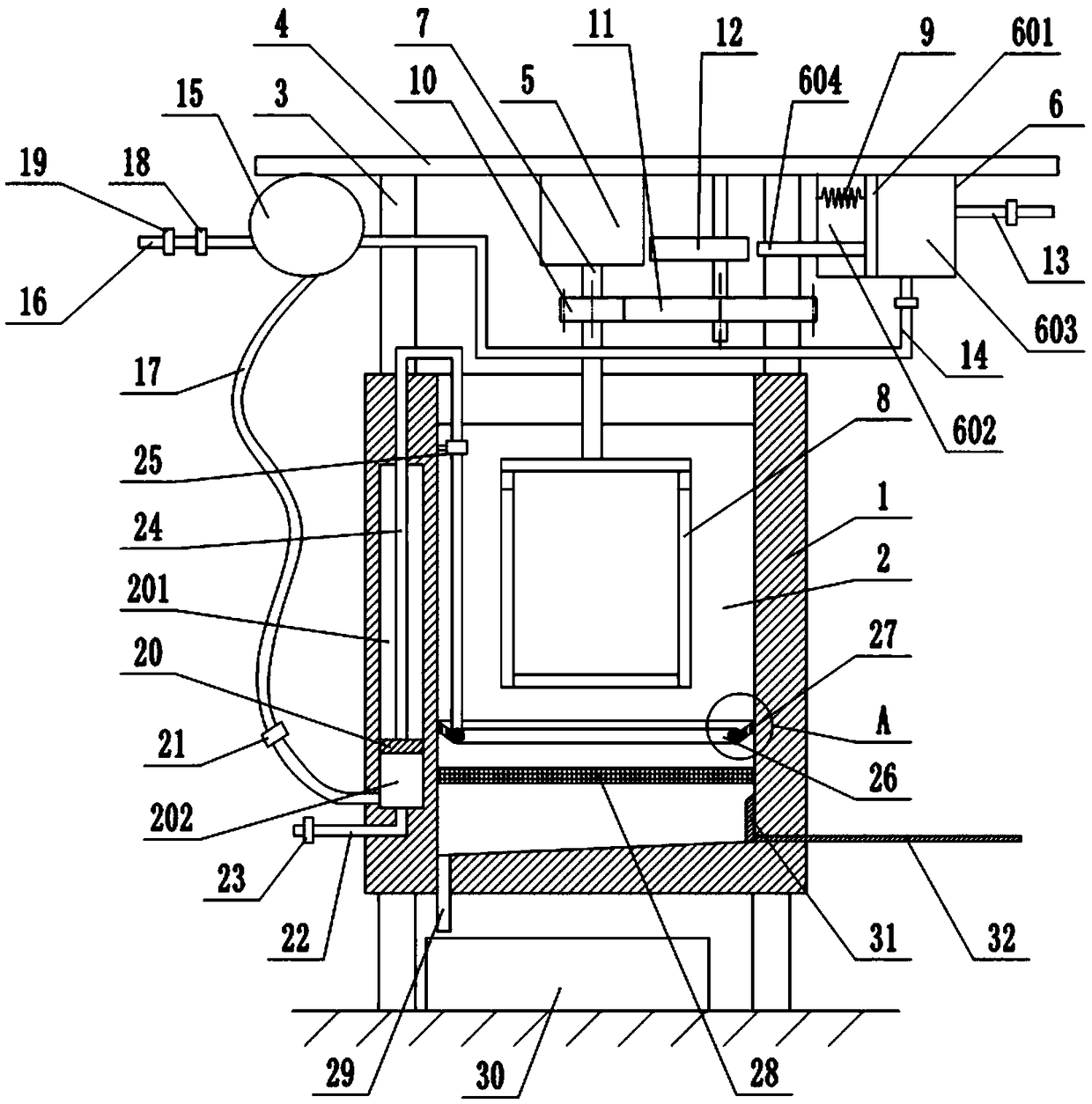
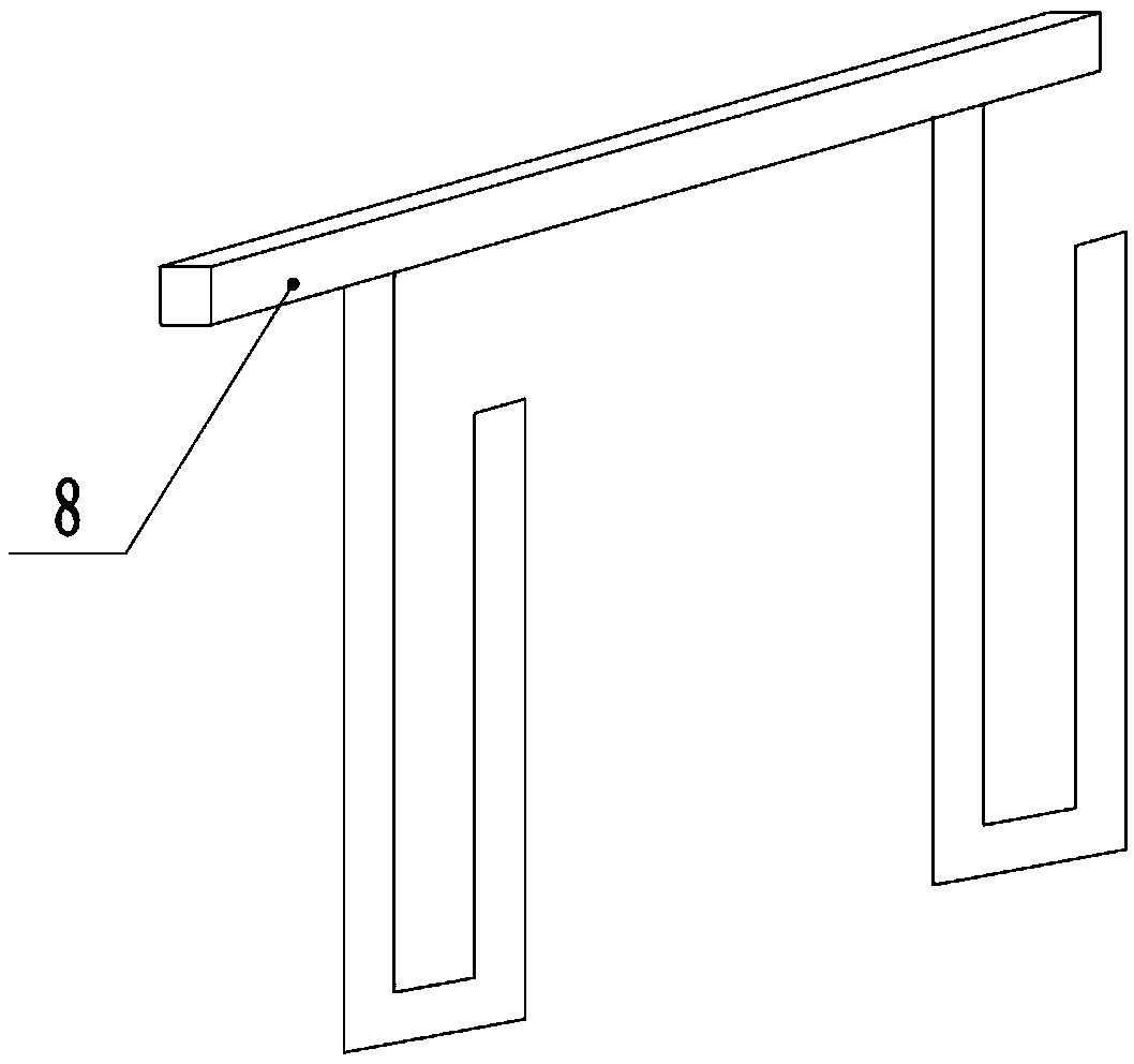
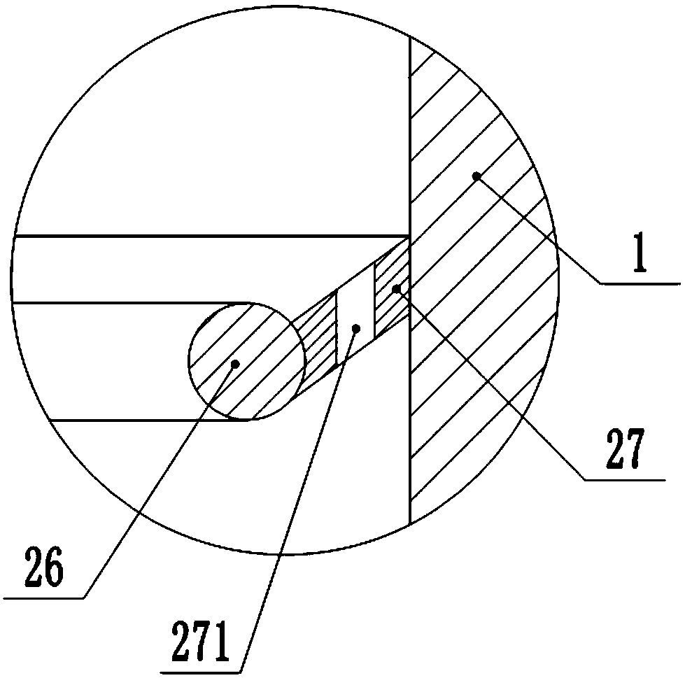
[0022] The reference signs in the drawings of the description include: tank body 1, honey shaker chamber 2, telescopic rod 3, support plate 4, motor 5, cylinder body 6, piston 601, left chamber 602, right chamber 603, piston rod 604 , rotating shaft 7, placement frame 8, spring 9, first gear 10, second gear 11, cam 12, air intake pipe 13, air outlet pipe 14, elastic air bag 15, deflation pipe 16, air delivery hose 17, air pressure valve 18, First air valve 19, plunger 20, upper chamber 201, lower chamber 202, second air valve 21, vent pipe 22, third air valve 23, U-shaped rod 24, scraper ring 25, annular ring 26, scraper Sheet 27, through hole 271, filter screen 28, honey outlet 29, collection tank 30, scraper 31, push rod 32.

[0023] The shake honey pot used in the honey cleaning method in the present embodiment is basically as figure 1 , figure 2 As shown, the honey shaking po...


PUM


Abstract

The invention relates to the technical field of honey production, and particularly discloses a honey cleaning method. The method comprises the following steps of: 1. removing a bee trough plate from abeehive and gently brushing the bees out on the bee trough plate with a soft brush; 2. putting the bee trough plate into a honey-shaking cavity, starting a motor, and shaking the honey while pressingthe outside air into an elastic airbag for storage; 3. after the shaking honey is finished, turning off the motor, putting the bee trough plate in the honey-shaking cavity back into the beehive, repeating steps 1 and 2; 4. after the last piece of the bee trough plate is processed, sending the air in the elastic air bag to a cavity provided in the side wall of a honey-shaking pot, and moving a blade to scrape off the adhered honey on the side wall of the honey-shaking pot; 5. pushing a push rod, moving the scraper set at the bottom of the honey-shaking cavity, and pushing the honey adhering tothe bottom wall of the honey-shaking pot to the honey outlet; 6. releasing the air in the cavity, resetting the blade, and pulling the push rod to reset; 7. taking away the honey. The honey cleaningmethod can scrape the honey adhered on the side wall and the bottom wall of the honey-shaking cavity, thereby reducing the waste of honey.

Description

technical field [0001] The invention relates to the technical field of honey production, and specifically discloses a honey cleaning method. Background technique [0002] When the beekeeper collects the honey in the beehive, he usually first takes out the beehive plate from the beehive, then puts the beehive plate into the honey shaker, uses the centrifugal force to make the honey in the beehive plate be thrown out, and the honey finally comes out of the beehive. The side wall of the honey shaker flows to the bottom of the honey shaker, and finally the beekeeper takes out the honey in the bottom of the honey shaker. In the above-mentioned process, because honey has a certain adhesiveness, therefore, a relatively large amount of honey is often adhered to the inner wall of the honey shaker. And when the beekeeper manually scrapes off the honey adhered on the inner wall, the arm of the beekeeper needs to be stretched into the inside of the honey shaker, which has the problems ...

Claims


Application Information

Patent Timeline
IPC IPC(8): A01K59/00B08B9/087
CPCA01K59/00B08B9/087
Inventor 岳光羽
Owner 永春县产品质量检验所福建省香产品质量检验中心国家燃香类产品质量监督检验中心福建
Why Eureka
Try Eureka