Hollow pedicle screw with oval side hole

A pedicle screw and oval technology, applied in the field of vertebral surgery, can solve problems such as uneven outflow of bone cement, and achieve the effects of reducing local resistance loss and high injection efficiency

Active Publication Date: 2020-01-21
CHANGZHOU WASTON MEDICAL APPLIANCE CO LTD
View PDF8 Cites 0 Cited by
  • Summary
  • Abstract
  • Description
  • Claims
  • Application Information

AI Technical Summary

Problems solved by technology

[0004] The present invention proposes a hollow pedicle screw with elliptical side holes, which can achieve the effect of equal flow of bone cement flowing out of each side hole with higher injection efficiency, and obtain the best holding force, so as to solve the existing problems. Problems such as uneven flow of bone cement caused by diameter round holes in the technology

Method used


Image

  • Hollow pedicle screw with oval side hole
  • Hollow pedicle screw with oval side hole
  • Hollow pedicle screw with oval side hole

Examples


Embodiment 1

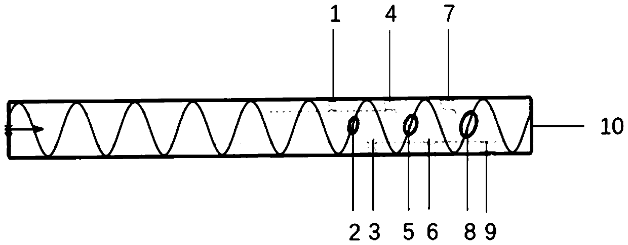
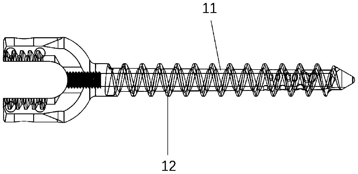
[0027] combine Figure 1-2 As shown, a hollow pedicle screw with an elliptical side hole includes a screw body 11, the screw body 11 is hollow and the end is penetrated; the screw body 11 is provided with an external thread section 12; the external thread section There are side holes distributed on the third of the distal end of 12, specifically nine bone cement outflow holes 1 to 9 penetrating through the unilateral side wall of the screw body, and three bone cement outflow holes are arranged along each thread, arranged at equal intervals , the size of bone cement injection hole 1 to hole 9 increases along the nail depth direction; that is, the size of the major and minor semi-axes of the elliptical hole increases in a parabolic manner.

[0028] The side holes are distributed along the thread line of the external thread segment 12, and there are 3 side holes in each circle with a mutual interval of 120°; the side holes are elliptical. The central axis of the side hole is per...

Embodiment 2

[0037] Two types of pedicle screws were designed according to the method of Example 1, and the hollow channels of the nails were 1.6 mm and 2.1 mm, respectively. The side holes of these two pedicle screws were optimized separately, so that the perfused bone cement could flow out evenly from each side hole.

[0038] The optimization schemes of the two hollow pedicle screws are shown in Table 1.

[0039] Table 1 screw optimization scheme

[0040]

[0041] Note: Table 1 is the screw optimization scheme, and 5 schemes are designed for the screws with the through hole diameters of 2.1mm and 1.6mm respectively. Among them, NO.01 and NO.06 are control groups with the same side hole size.

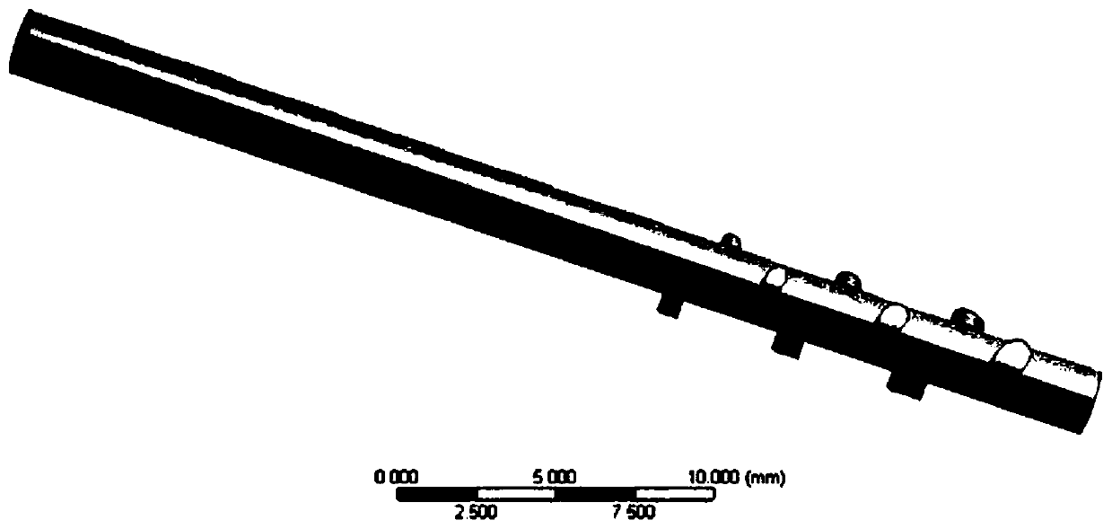
[0042] Such as image 3 As shown in , the inner channel area of ​​the hollow pedicle screw was extracted to establish a flow field model.

[0043] Divide the tetrahedral grid for the flow field area in the nail channel, such as Figure 4 As shown, a total of 283,362 nodes and 1,579,725 unit...


PUM


Abstract

The invention relates to the technical field of vertebra surgeries and particularly relates to an oval side-hole type hollow pedicle screw. A screw body of the oval side-hole type hollow pedicle screwis hollow, and the tail end of the oval side-hole hollow pedicle screw is perforated; side holes are distributed in a 1 / 3 section of a far end of a threaded section of the oval side-hole hollow pedicle screw along a spiral line, the interval between two adjacent side holes is 120 degrees, central shafts of the holes are vertical to a longitudinal shaft of the screw body and have same intervals, the ratio of short and long semi-axes of the oval side holes is 0.75-0.85, the long axes of the oval holes are parallel to the direction of the spiral line, and the sizes of the oval holes gradually increase along the length of the screw. By utilizing the oval side holes, the side holes are as big as possible when the strength of the screw body is guaranteed, and the loss of local resistance of a fluid can be reduced under the flow guiding direction of the oval holes; and by utilizing the oval side holes with the sizes which gradually increase, bone cement can be uniformly distributed along thedirection of the screw body.

Description

technical field [0001] The invention relates to the technical field of vertebra surgery, in particular to a hollow pedicle screw with an oval side hole. Background technique [0002] For elderly patients with vertebral diseases, solid pedicle screws are difficult to obtain better holding force due to osteoporosis, so it is often necessary to use hollow pedicle screws (Fenestrated Pedicle Screw, FPS) with side holes to Bone cement is injected to increase the grip of the nail in the bone. In 2005, Yazu et al first found through experimental research that the pull-out resistance of hollow side hole pedicle screws was significantly increased compared with conventional pedicle screws (Conventional Pedicle Screw, CPS). However, due to the high viscosity of the bone cement and the high pressure of the medium around the hole during the perfusion process to hinder the outflow of the bone cement, the use of holes with equal pore diameters and equal spacing will cause obvious unevenne...

Claims


Application Information

Patent Timeline
Patent Type & Authority Patents(China)
IPC IPC(8): A61B17/70
CPCA61B17/7032A61B17/7098
Inventor 王君胡晓文韦冬王江南周锦
Owner CHANGZHOU WASTON MEDICAL APPLIANCE CO LTD
Why Eureka
Try Eureka