Airflow transportation method for vertical roller mill airflow device of cement raw material slag

A vertical roller mill and cement raw material technology, applied in cement production, grain processing, etc., can solve the problems of increased wear of nozzle rings, increased number of shutdowns for maintenance, and increased operating power of system fans, so as to reduce the probability of circulation and cycle The effect of reducing the number of times, reducing airflow turbulence, and low conveying speed

Inactive Publication Date: 2015-07-01
LUOYANG MINING MACHINERY ENG DESIGN & RES INST
View PDF5 Cites 0 Cited by
  • Summary
  • Abstract
  • Description
  • Claims
  • Application Information

AI Technical Summary

Problems solved by technology

[0002] Looking at domestic and foreign vertical roller mills, the finished materials are obtained through the airflow dispersion, drying and pneumatic conveying of the airflow conveying device. The wear-resistant guide vanes of the nozzle ring need to have a suitable horizontal angle. The size of the angle It has a great influence on the dispersion of cakes or granules, the drying of the material surface and the effect of powder pneumatic conveying, and the angle changes with the composition of the material, the moisture content of the material and the air velocity. It must pass the vertical roller mill test bench experiment and CFD Only by analysis can it be determined, and most of the current vertical roller mill airflow conveying devices have nozzle rings with wear-resistant guide blades whose angles cannot be adjusted, which affects the airflow conveying effect of the vertical roller mill and the long-term stable operation of the equipment; secondly, At present, the equal-width structural design of the wear-resistant guide blades of the nozzle ring makes the front and rear widths of the cross-section consistent, which increases the local resistance loss of the nozzle ring and the inlet resistance loss of the nozzle ring, resulting in an increase in the operating power of the system fan, which is not conducive to energy saving and consumption reduction. macro goals
Moreover, the excessively high flow velocity of the nozzle ring will also cause the wear of the nozzle ring to increase, and the number of downtime maintenance will increase, which is not conducive to ensuring the annual operation rate target of the vertical roller mill; thirdly, although the double air inlet structure is widely used in the industry However, the shape and size of the air inlet vary greatly and the internal flow guide and material guide structure design of the air inlet cannot form a stable pressure difference and a stable air velocity in the inner area of ​​​​the air inlet, so it is impossible to form a stable air flow. field, so that it cannot become a real high-efficiency air delivery device

Method used


Image

  • Airflow transportation method for vertical roller mill airflow device of cement raw material slag
  • Airflow transportation method for vertical roller mill airflow device of cement raw material slag
  • Airflow transportation method for vertical roller mill airflow device of cement raw material slag

Examples


Embodiment 1

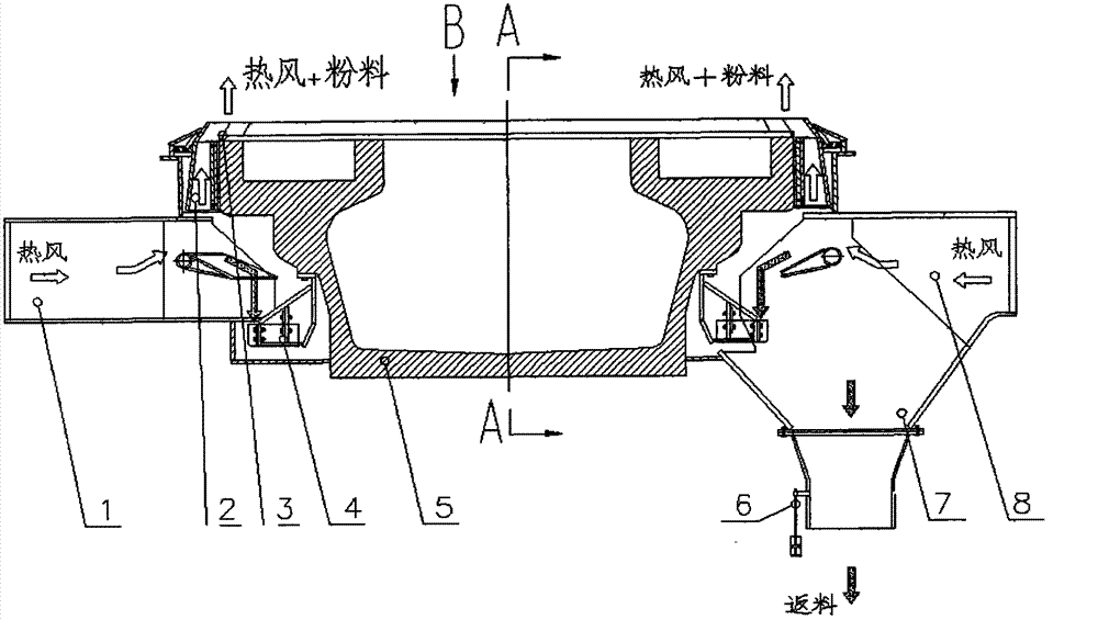
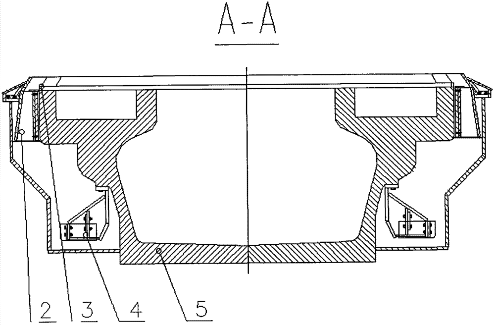
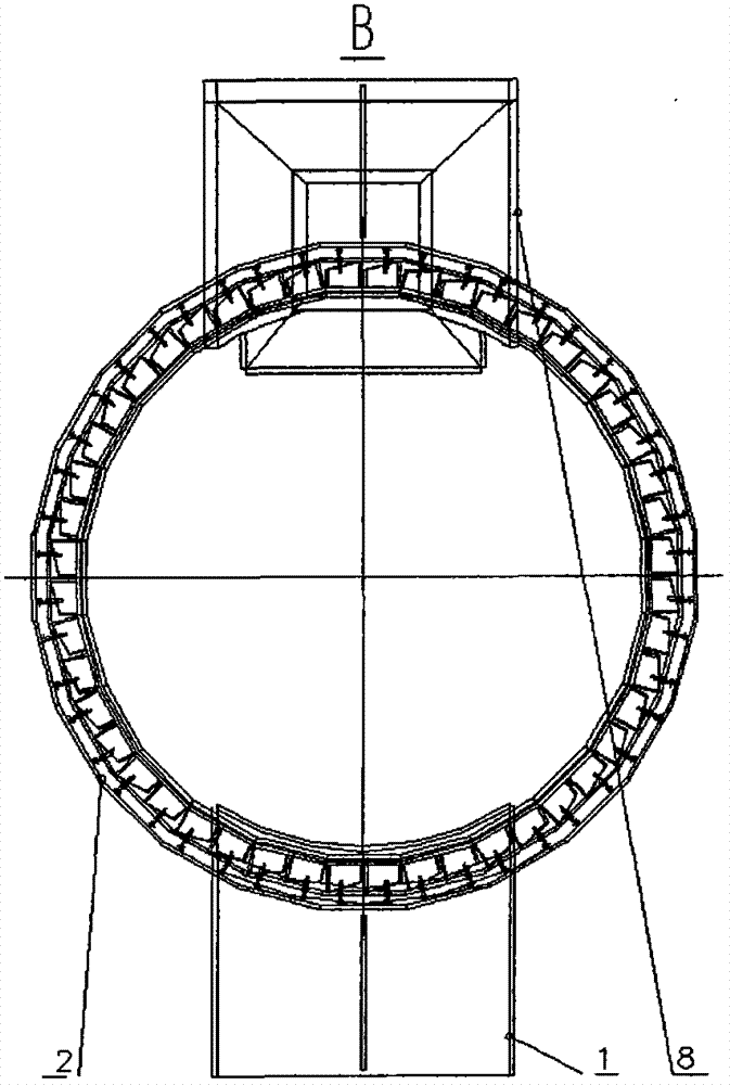
[0035] Such as figure 1 As shown: the lower barrel body is set on the middle and lower part of the periphery of the millstone 5, the nozzle ring 2 is set on the upper part of the periphery of the millstone 5, and the material retaining ring 3 is set on the upper edge of the millstone 5; the two sides of the lower barrel body of the millstone 5 are symmetrically reserved for air inlets, and one side The outlet end of the free-end air inlet 1 box is set in the air inlet; the outlet end of the air inlet 8 at the return end is set in the air inlet on the other side, and the return collection cone 7 is set at the lower port of the air inlet 8 at the return end. The lower opening of the return material collection cone 7 is provided with an air-lock flap ash unloading valve 6; a boss is arranged in the middle of the periphery of the grinding disc 5, and at least eight wear-resistant scrapers 4 are evenly distributed and fixed under the boss, and the wear-resistant scraper 4 is arrange...

Embodiment 2

[0037] Such as Figure 1-9 Shown: Free end upper cover plate 9 is set above the free end air inlet 1 box body, free end lower cover plate 10 is set below, free end upper cover plate 9 and free end lower cover plate 10 are respectively set free end left The baffle plate 11, the right side is provided with the free end right baffle plate 13; the air inlet 1 box body of the free end is set as two box sections, the inlet end is provided with an air inlet section, and the outlet end is provided with a wind guide section; the air inlet section box body is free The middle part between the end upper cover plate 9 and the free end lower cover plate 10 is provided with a free end middle partition 12; Annular material guide reinforcement tube 14, guide material upper wear-resistant plate 15 is arranged above the guide material reinforcement tube 14, guide material lower wear-resistant plate 16 is arranged below, guide material lower wear-resistant plate 16 and guide material upper wear-r...

Embodiment 3

[0039] Such as figure 1 .10.11.12.13 shows: the nozzle ring 2 is an annular cavity, and at least eight units are arranged in the annular cavity, and the hot air flow passes between each unit. The nozzle ring support plate 25 is arranged on the outer side, and at least six pairs of corresponding grooves are arranged on the surface of the nozzle ring inner baffle 27 and the nozzle ring support plate 25. Nozzle ring wear-resistant guide vanes 26 are arranged in the groove; a nozzle ring adjustment plate 24 is arranged on the upper end of the inner baffle plate 27 of the nozzle ring, and a wind guide material baffle is arranged on the upper end of the nozzle ring support plate 25 of the nozzle ring 2 .


PUM


Abstract

An airflow transportation method for a vertical roller mill airflow device of cement raw material slag. A millstone top edge is provided with a material barrier ring; a nozzle ring is arranged at an upper part of a lower barrel body of the millstone; both sides of the lower barrel of the millstone are symmetrically preserved with an air intake; a lower port of a feed returning end air intake box is provided with a revert collection cone and an air-lock turnover plate unloading valve; fixed wear scraping plates are uniformly arranged under the millstone; for working, heat flow upraises into the nozzle ring, and a nozzle ring wear-resistant guide vane inclined in a direction adjusts the airflow to rotates at high speed, impacts, shears and overflows a block material extruded into a cake at an external side of the material barrier ring; the moisture of the block material rapidly evaporates and disperses into powder after high temperature; the powder rises to the top of the mill for further classification process; the millstone drives the wear scraping plates fixed below the periphery; coarse particles and metal impurities at the middle and bottom of the lower barrel are scraped into a returning material collection cone; and air-lock turnover plate unloading valve discharges the coarse particles and metal impurities out of the mill.

Description

technical field [0001] The invention relates to a vertical roller mill for cement raw material and slag, in particular to a vertical roller mill airflow device for cement raw material slag and an airflow delivery method thereof. Background technique [0002] Looking at domestic and foreign vertical roller mills, the finished materials are obtained through the airflow dispersion, drying and pneumatic conveying of the airflow conveying device. The wear-resistant guide vanes of the nozzle ring need to have a suitable horizontal angle. The size of the angle It has a great influence on the dispersion of cakes or granules, the drying of the material surface and the effect of powder pneumatic conveying, and the angle changes with the composition of the material, the moisture content of the material and the air velocity. It must pass the vertical roller mill test bench experiment and CFD Only by analysis can it be determined, and most of the current vertical roller mill airflow conv...

Claims


Application Information

Patent Timeline
Patent Type & Authority Patents(China)
IPC IPC(8): B02C15/00B02C23/18
CPCY02P40/10
Inventor 张廷龙张路明王军吴新民赵智峰李客夏莹
Owner LUOYANG MINING MACHINERY ENG DESIGN & RES INST
Why Eureka
Try Eureka