Heat dissipation structure

a heat dissipation structure and heat dissipation technology, applied in the direction of cooling/ventilation/heating modification, semiconductor/solid-state device details, semiconductor devices, etc., can solve the problem of shortening the life and achieve the effect of improving the heat dissipation performan

Inactive Publication Date: 2005-08-18
CHAUN CHOUNG TECH
View PDF2 Cites 15 Cited by
  • Summary
  • Abstract
  • Description
  • Claims
  • Application Information

AI Technical Summary

Benefits of technology

[0004] The present invention provides a heat dissipation structure with enhanced heat dissipation performance.
[0005] The present invention further provides a heat dissipation structure of which the operation power of the heat pipes is mitigated, such that the lifetime of the heat pipes is prolonged.
[0006] The heat dissipation structure provided by the present invention includes a heat sink installed on a heat generating electronic device and a plurality of heat pipes. Proximal ends of the heat pipes are located on the heat sink, while distal ends of the heat pipes extend outside of the heat sink and are connected to a set of fins 3. The heat dissipation device further comprises a plurality of thermal conductor blocks formed on the heat sink at two sides of the heat pipes, such that a portion of the heat generated by the electronic device is absorbed by the thermal conductor blocks to mitigate the operation power of the heat pipes.

Problems solved by technology

The high temperature caused by excessive thermal energy may even cause phase transition of the working fluid in the heat pipes 2a to shorten the lifetime thereof.

Method used


Image

  • Heat dissipation structure
  • Heat dissipation structure
  • Heat dissipation structure

Examples


Embodiment Construction

[0019] Reference will now be made in detail to the preferred embodiments of the present invention, examples of which are illustrated in the accompanying drawings. Wherever possible, the same reference numbers are used in the drawings and the description to refer to the same or like parts.

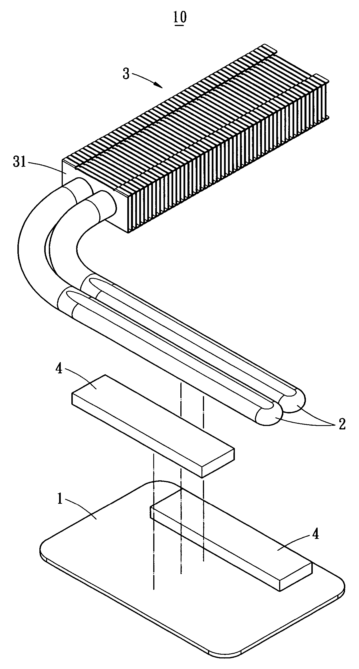
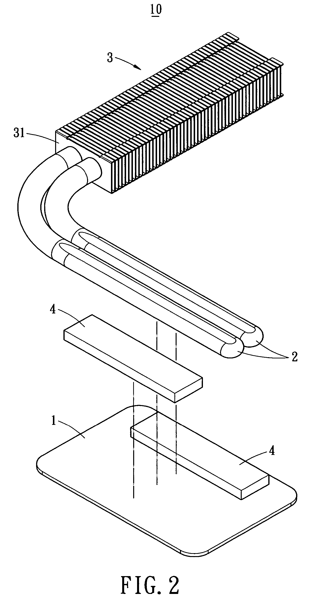
[0020] The present invention provides a heat dissipation structure. As shown in FIG. 2, the heat dissipation structure 10 includes a heat sink 1 attached on a central processing unit (CPU) 51. The heat sink 1 preferably fabricated from aluminum or copper, for example.

[0021] The heat dissipation structure 10 includes a plurality of heat pipes 2. In this embodiment, the heat pipes 2 are in L shape and include wick structures and working fluids filled therein. One ends of the heat pipes 2 are located on the heat sink 1, while the other ends of the heat pipes 2 extend outside of the heat sink 1 and are connected to a set of fins 3. The set of fins 3 includes a plurality of fins 31 equally spaced from ...


PUM


Abstract

A heat dissipation structure includes a heat sink installed over a heat generating electronic device and a plurality of heat pipes. Proximal ends of the heat pipes are located on the heat sink, and distal ends of the heat pipes extend outside of the heat sink and are connected to a set of fins. The structure is characterized in a plurality of conductor blocks formed on the heat sink at two sides of each heat pipe to aid heat absorption of the heat pipe. Therefore, the lifetime of the heat pipes are prolonged, and the heat dissipation performance is enhanced.

Description

BACKGROUND OF THE INVENTION [0001] The present invention relates to heat dissipation structure, and more particular, to a heat dissipation device used for dissipating heat generated by an electronic device. [0002] The conventional heat dissipation device 10a used in a central processing unit (CPU) 51a of a printed circuit board 5a is illustrated in FIG. 1. The heat dissipation device 10a includes a heat sink 1a installed on the CPU 51a and a plurality of heat pipes 2a. The material for fabricating the heat sink 1a includes aluminum. The heat pipes 2a include wick structures and working fluids filled therein, such that thermal energy is absorbed and discharged by the flow and phase transition of the working fluids. As shown, one ends of the heat pipes 2a are located on the heat sink 1a, and the other ends of the heat pipes 2a extend outside of the heat sink 1a. A set 3a of fins 31a is installed along one side of the heat pipes 2a. A fan (not shown) may be installed at one side of the...

Claims


Application Information

Patent Timeline
Patent Type & Authority Applications(United States)
IPC IPC(8): H01L23/427H05K7/20
CPCH01L23/427H01L2924/0002H01L2924/00F28D15/0233F28D15/0275
Inventor I-YUNG, LINMENG-CHENG, HUANG
Owner CHAUN CHOUNG TECH
Why Eureka
Try Eureka