Two-stage air compressor and dust collector

An air compressor and diffuser technology, applied in the field of two-stage air compressors and vacuum cleaners, can solve the problems of reducing the vacuum degree of vacuum cleaners, reducing suction power, and increasing motor noise, so as to reduce local resistance loss and avoid airflow large loss effect

Pending Publication Date: 2022-07-22
GREE ELECTRIC APPLIANCES INC
View PDF0 Cites 0 Cited by
  • Summary
  • Abstract
  • Description
  • Claims
  • Application Information

AI Technical Summary

Problems solved by technology

[0002] At present, most vacuum cleaners use single-stage centrifugal or single-stage mixed-flow impellers as pneumatic components (that is, air compressors), which are characterized by simple structure, high speed, high noise, and relatively small pressure ratio. It is not enough to clean large particles. Thoroughly, due to its hand-held and portable use characteristics, the outer diameter of the motor of the air compressor it has is subject to certain restrictions, so it is not advisable to increase the pressure ratio by increasing the outer diameter of the impeller. At the same time, increasing the outer diameter of the impeller will cause obvious motor noise Increase, the high-efficiency point of the impeller is biased towards large flow, beyond the applicable flow range of the vacuum cleaner
In view of the aforementioned deficiencies, a two-stage compressor using a two-stage impeller appeared in the prior art, but the air outlet of the two-stage compressor of the existing two-stage impeller is a radial air outlet, which causes the air flow to flow at the outlet end of the compressor. The loss in the interior is relatively large, which reduces the vacuum of the vacuum cleaner and reduces the suction power

Method used


Image

  • Two-stage air compressor and dust collector
  • Two-stage air compressor and dust collector
  • Two-stage air compressor and dust collector

Examples


Embodiment Construction

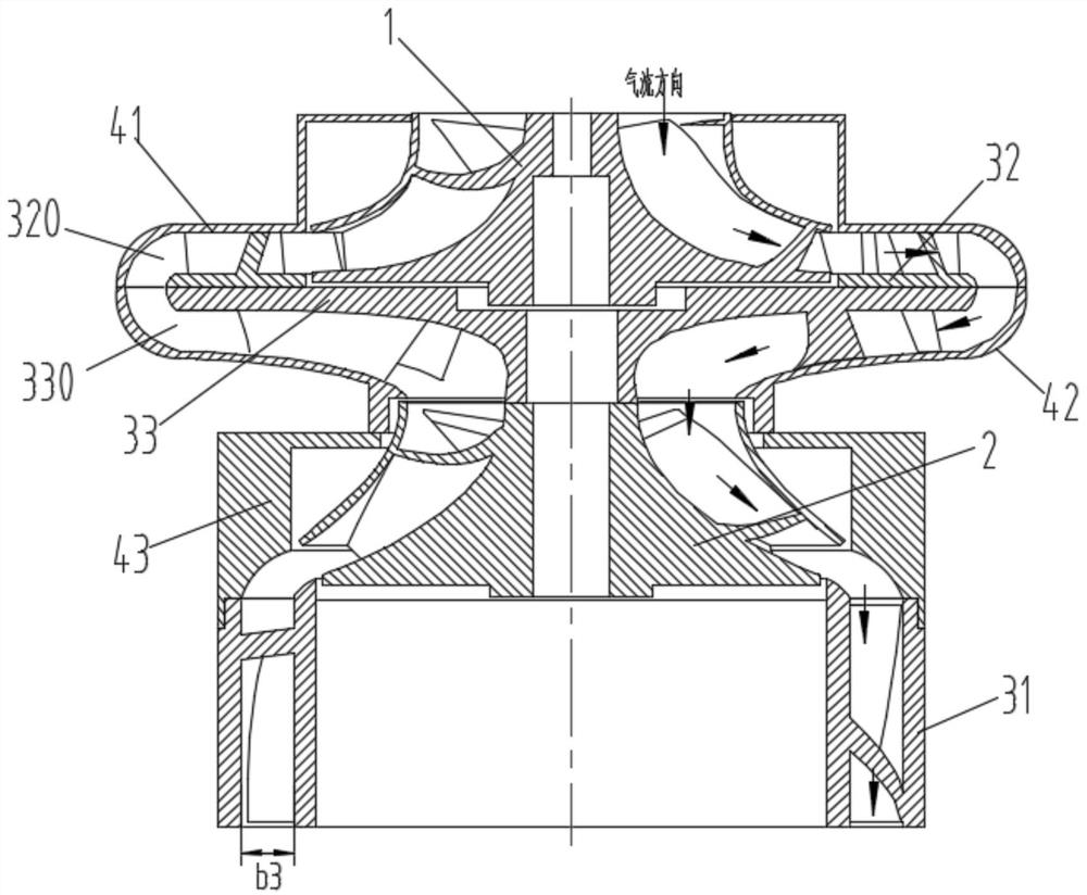
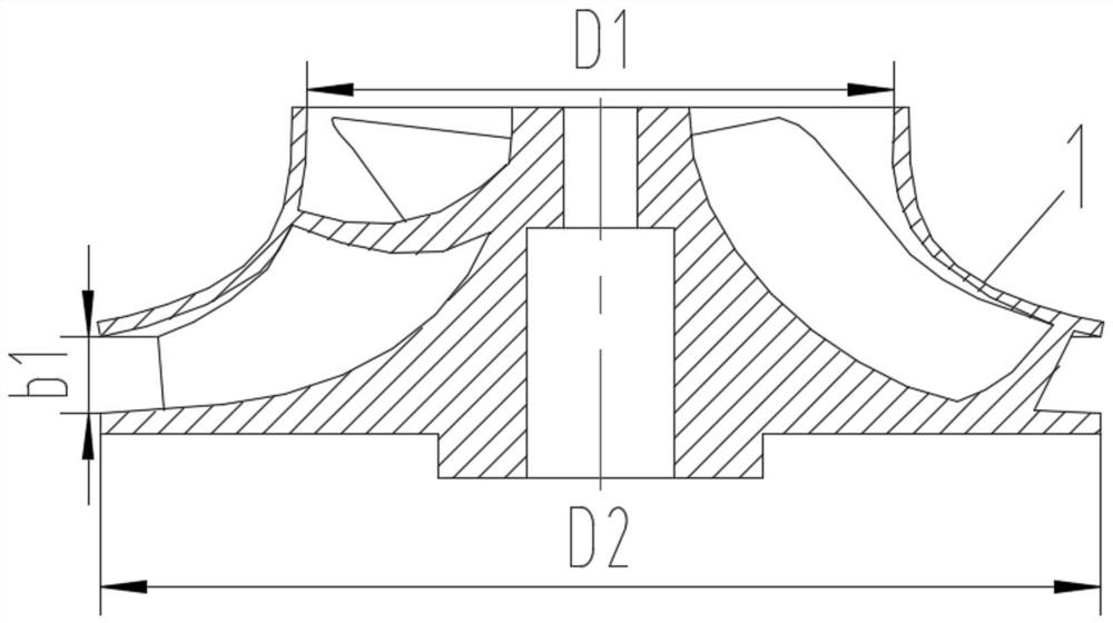
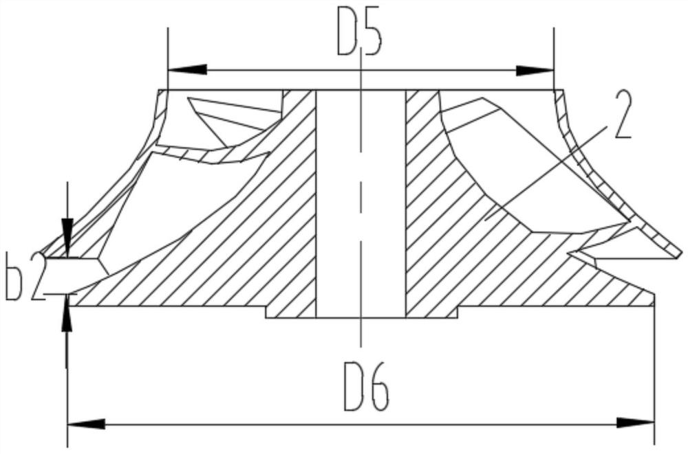
[0029] see in combination Figure 1 to Figure 8 As shown, the present invention provides a two-stage air compressor, comprising a sealed shell, a first-stage impeller 1 and a second-stage impeller 2 in the sealed shell, and the first-stage impeller 1 and the second-stage impeller 2 are coaxial Arrangement, the air outlet side of the secondary impeller 2 is connected with a secondary diffuser 31, and the secondary diffuser 31 is an axial diffuser, so that the flow direction of the outlet air flow is the same as that of the secondary impeller. 2 are parallel to the central axis. In this technical solution, the airflow compressed by the first-stage impeller 1 and the second-stage impeller 2 can flow out parallel to the central axis of the second-stage impeller 2 when the wind is discharged, which can reduce the local impact caused by turning. resistance loss, thereby improving the vacuum degree and suction power and improving the performance of the vacuum cleaner to which it is ...


PUM

PropertyMeasurementUnit
Axial lengthaaaaaaaaaa
Exit widthaaaaaaaaaa
Axial lengthaaaaaaaaaa

Abstract

The two-stage air compressor comprises a sealing shell, a first-stage impeller and a second-stage impeller, the first-stage impeller and the second-stage impeller are located in the sealing shell, the first-stage impeller and the second-stage impeller are coaxially arranged, the air outlet side of the second-stage impeller is connected with a second-stage diffuser, the second-stage diffuser is an axial diffuser, and the first-stage impeller and the second-stage impeller are coaxially arranged. And the flow direction of the air outlet airflow is parallel to the central axis of the second-stage impeller. According to the invention, airflow compressed by the first-stage impeller and the second-stage impeller can flow out in parallel with the central axis of the second-stage impeller during air outlet, so that the phenomenon of relatively large airflow loss caused by a radial air outlet mode in the prior art is effectively avoided.

Description

technical field [0001] The invention belongs to the technical field of air compressor manufacturing, and in particular relates to a two-stage air compressor and a vacuum cleaner. Background technique [0002] At present, most vacuum cleaners use single-stage centrifugal or single-stage mixed-flow impellers as pneumatic components (ie, air compressors), which are characterized by simple structure, high speed, high noise, and relatively small pressure ratio, which are not enough for cleaning large particles. Thoroughly, due to its hand-held and portable use characteristics, the outer diameter of the motor of the air compressor is limited to a certain extent, so the method of increasing the pressure ratio by increasing the outer diameter of the impeller is not advisable, and at the same time increasing the outer diameter of the impeller, the motor noise is obvious. Increase, the high-efficiency point of the impeller is biased towards the large flow area, which is beyond the app...

Claims


Application Information

Patent Timeline
IPC IPC(8): F04D17/12F04D29/28F04D29/30F04D29/44
CPCF04D17/12F04D29/284F04D29/30F04D29/444F04D29/441
Inventor 陈彬杨国蟒宣卫豪肖勇王越
Owner GREE ELECTRIC APPLIANCES INC
Why Eureka
Try Eureka