
Clamping and conveying device used for on-line cooling device of section mill

A technology of cooling device and rolling mill, which is applied in the direction of workpiece cooling device, metal rolling, metal rolling, etc. It can solve the problems of cooling device wear, profile steel offset, machine vibration, etc., and achieve the effect of preventing offset

Active Publication Date: 2018-11-13
马鞍山市银鼎机械制造股份有限公司
View PDF7 Cites 2 Cited by
  • Summary
  • Abstract
  • Description
  • Claims
  • Application Information

AI Technical Summary

Problems solved by technology

[0005] The purpose of the present invention is to solve the lack of an effective pinch device for the cooled section steel in the prior art, and the section steel is easily affected by the vibration of the machine on the way into the cooling device, so that the section steel itself is greatly deflected, and the The problem of wear caused by the cooling device, and a pinch device for the on-line cooling device of the section steel mill is proposed

Method used


Image

  • Clamping and conveying device used for on-line cooling device of section mill
  • Clamping and conveying device used for on-line cooling device of section mill
  • Clamping and conveying device used for on-line cooling device of section mill

Examples


Embodiment Construction

[0022] The following will clearly and completely describe the technical solutions in the embodiments of the present invention with reference to the accompanying drawings in the embodiments of the present invention. Obviously, the described embodiments are only some, not all, embodiments of the present invention.

[0023] In describing the present invention, it should be understood that the terms "upper", "lower", "front", "rear", "left", "right", "top", "bottom", "inner", " The orientation or positional relationship indicated by "outside", etc. is based on the orientation or positional relationship shown in the drawings, and is only for the convenience of describing the present invention and simplifying the description, rather than indicating or implying that the referred device or element must have a specific orientation, so as to Specific orientation configurations and operations, therefore, are not to be construed as limitations on the invention.

[0024] refer to Figure ...


PUM


Abstract

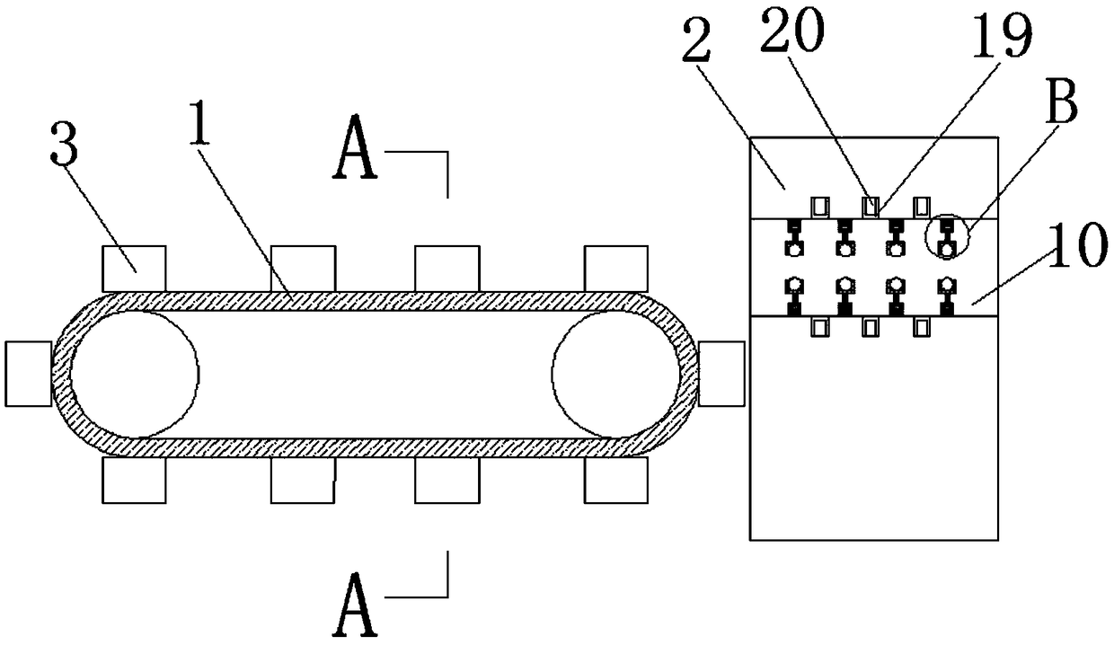
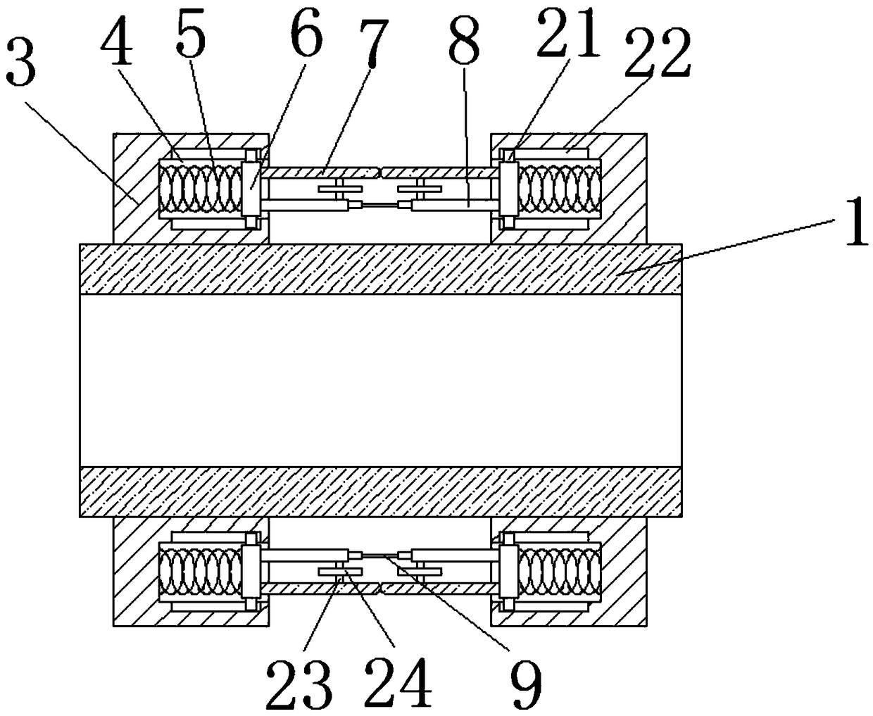
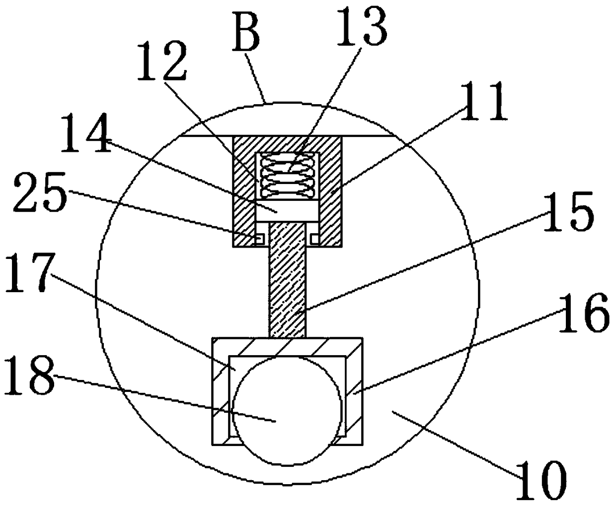
The invention discloses a clamping and conveying device used for an on-line cooling device of a section mill. The clamping and conveying device comprises a conveyer belt and a carrier arranged on oneside of the conveyer belt; a plurality of clamping and conveying components are uniformly arranged on the conveyer belt at equal intervals; each clamping and conveying component comprises two clampingand conveying blocks which are fixedly connected to the conveyer belt; opposite sides of every two clamping and conveying blocks are provided with clamping and conveying grooves; the groove bottom ofeach clamping and conveying groove is fixedly connected with a first spring, and the other end of the first spring is fixedly connected with a clamping and conveying plate; the end, which is far awayfrom the corresponding first spring, of each clamping and conveying plate is symmetrically connected with a first clamping and conveying pin and a second clamping and conveying pin; the ends, far away from the corresponding first spring, of every two first clamping and conveying pins are arc surfaces which are resisted against each other; and a telescopic rod is arranged between opposite ends ofevery two second clamping and conveying pins. The clamping and conveying device is simple in structure and convenient to operate; section steel is limited through the clamping and conveying components, so that the section steel is prevented from deviating greatly to cause unnecessary abrasion to the cooling device; and besides, the carrier of the cooling device can be applicable to section steel of different sizes.

Description

technical field [0001] The invention relates to the technical field of metallurgy and rolling steel, in particular to a pinch device for an online cooling device of a section steel rolling mill. Background technique [0002] Controlled cooling technology has become one of the most critical technologies to reduce the alloy content of materials and improve the mechanical properties of materials, and has been recognized as the development direction of the metallurgical industry at home and abroad. Controlled cooling technology has been successfully applied in the field of strip, bar and wire, and has gradually become a mature technology. However, due to the complex cross-section of section steel, especially the online controlled cooling of H-section steel, it is easy to have uneven cooling, which will affect the quality of the rolled piece. The uniformity of cross-sectional shape and performance, so there are few cases of successful application of section steel cooling technolo...

Claims


Application Information

Patent Timeline
IPC IPC(8): B21B45/02B21B39/02
CPCB21B39/02B21B45/0209B21B2045/0221
Inventor 夏明星
Owner 马鞍山市银鼎机械制造股份有限公司
Learn More