Method for producing a plain bearing bush

A sliding shaft and sliding layer technology, applied in sliding contact bearings, rotating bearings, shafts, etc., can solve the problem of not specifying the radial sequence setting, etc., and achieve the effect of reducing finishing and eliminating creep.

Active Publication Date: 2018-11-13
MIBA SINTER AUSTRIA
View PDF12 Cites 3 Cited by
  • Summary
  • Abstract
  • Description
  • Claims
  • Application Information

AI Technical Summary

Problems solved by technology

However, this publication does not indicate in what radial order the layers are arranged

Method used


Image

  • Method for producing a plain bearing bush
  • Method for producing a plain bearing bush
  • Method for producing a plain bearing bush

Examples


Embodiment Construction

[0023] As an introduction, it should first be explained that in the various embodiments described differently, the same reference numerals or the same component names are provided for the same components, wherein the disclosure content contained in the entire description can be used according to the meaning to the same parts provided with the same reference numbers or the same component names. Moreover, the orientation descriptions selected in the specification, such as up, down, side, etc., are relative to the direct description and the accompanying drawings shown, and when the orientation changes, these orientation descriptions can be transferred to new orientation.

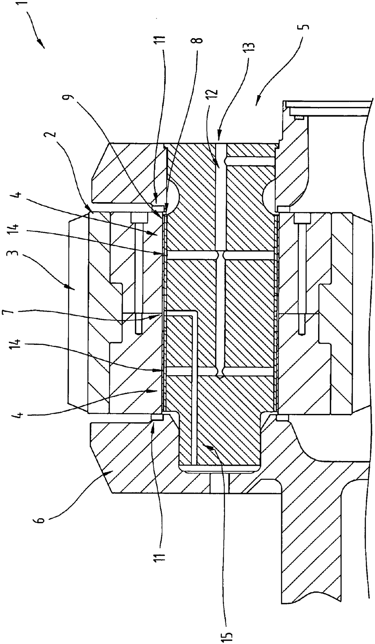
[0024] figure 1 Shown is a cross-sectional view of a part of a wind turbine drive 1 . The wind turbine gear 1 is in particular designed in the form of a (simple) planetary gear.

[0025] As is known, a wind power plant comprises a tower, on the upper end of which a nacelle is arranged, in which nacelle a rot...


PUM


Abstract

The invention relates to a method for producing a plain bearing bush (4) whereby a flat supporting metal layer (8) is provided, an anti-friction layer (9) is provided on this supporting metal layer (8) to produce a flat composite material, and the flat composite material is then rolled into the shape of the plain bearing bush (4) in such a way that the supporting metal layer (8) in the plain bearing bush (4) is disposed radially underneath the anti-friction layer (9). The invention further relates to a plain bearing bush (4) produced by this method.

Description

technical field [0001] The invention relates to a method for producing a sliding bushing, according to which a flat supporting metal layer (Stuetzmetallschicht) is produced, on which a sliding layer is arranged for the production of a flat composite material, and the flat composite material is subsequently The roll of material is pressed into the shape of the sliding bushing. [0002] Furthermore, the invention relates to a sliding bush rolled from composite material, comprising a supporting metal layer and a sliding layer. [0003] The invention also relates to a shaft, in particular a planetary pin for a wind power plant transmission, which has a sliding bush. [0004] Furthermore, the invention relates to a transmission for a wind power plant having at least one gear wheel which is arranged on a shaft, wherein a bearing point with a sliding bushing is arranged between the gear wheel and the shaft. Background technique [0005] Sliding bushings are usually designed in su...

Claims


Application Information

Patent Timeline
Patent Type & Authority Applications(China)
IPC IPC(8): B21D5/08B23P15/00F16C33/12F16C33/14
CPCF03D80/70F16C33/1055F16C33/125F16C2220/44F16H2057/085B21D5/08B23P15/00F16C33/14F16C2361/61F16C33/046F16C33/1025F16C33/122F16C2226/14F16C2226/36F16C2360/31F16C17/02F16C33/04F16H1/28B23K2101/04F16H57/0479
Inventor J·S·赫茨尔
Owner MIBA SINTER AUSTRIA
Why Eureka
Try Eureka