Automobile accessory cutting and chamfering device

A technology for auto parts and chamfering devices, which is applied in other manufacturing equipment/tools, metal processing, manufacturing tools, etc., and can solve the problems of low processing efficiency and a large number of manual participation.

Pending Publication Date: 2018-11-13
重庆辉海科技有限公司
View PDF6 Cites 0 Cited by
  • Summary
  • Abstract
  • Description
  • Claims
  • Application Information

AI Technical Summary

Problems solved by technology

The traditional processing method generally divides a long pipe at equal distances, and then uses an angle grinder to grind ...

Method used


Image

  • Automobile accessory cutting and chamfering device
  • Automobile accessory cutting and chamfering device
  • Automobile accessory cutting and chamfering device

Examples


Embodiment 1

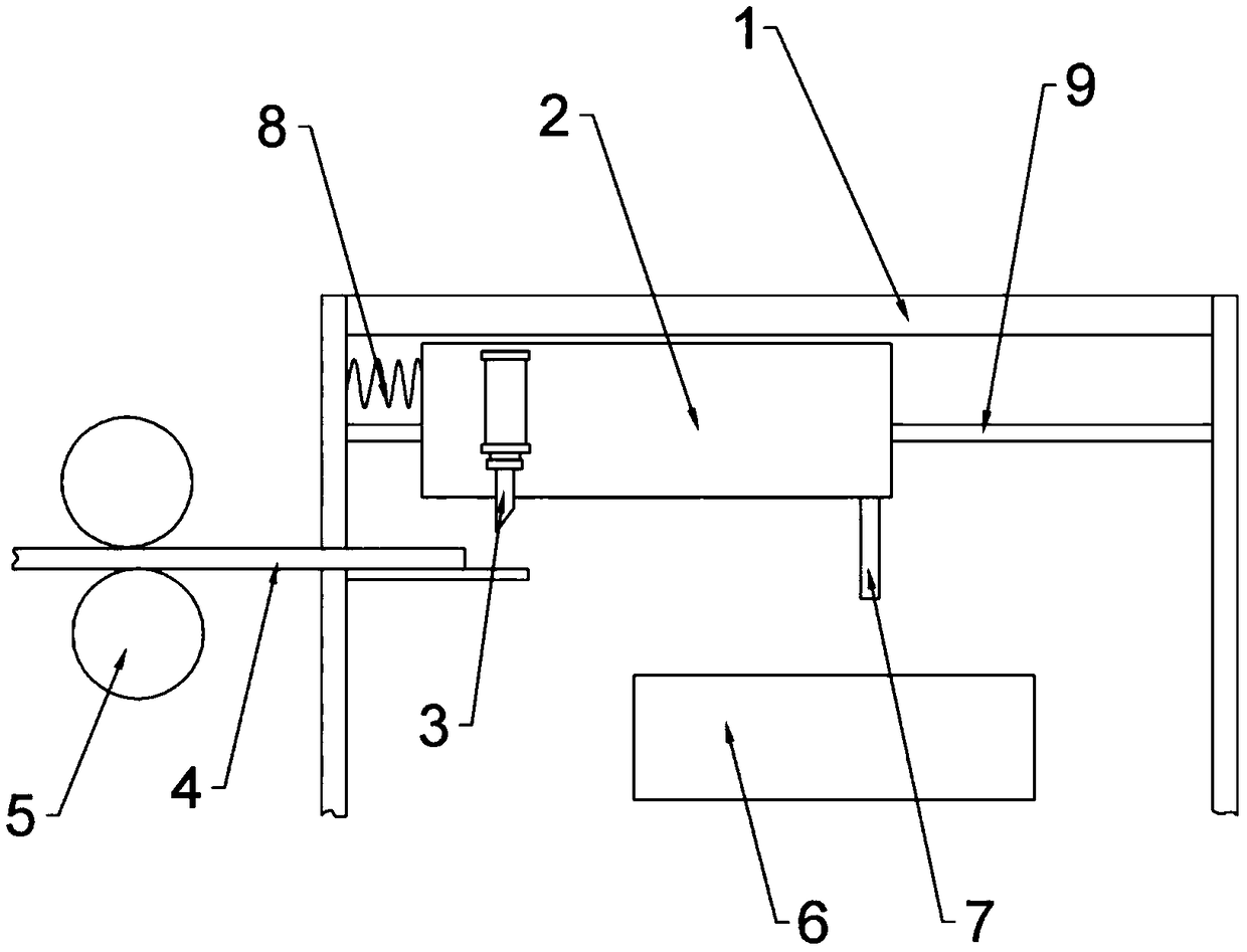
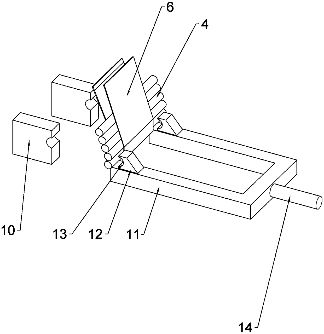
[0019] This embodiment is basically as attached figure 1 and figure 2 Shown: a cutting and chamfering device for auto parts 4, including a frame 1 and a torsion spring. One end of the frame 1 is provided with a feeding mechanism, and the feeding mechanism in this embodiment is two feeding rollers 5. A cutting mechanism is provided on the frame 1, and a blanking channel 6 is provided below the cutting mechanism, and a discharge port that only allows a single auto part 4 to pass is provided below the cutting device. A baffle is hinged at the discharge port, and the baffle passes through The torsion spring is connected with the blanking channel, and there is a clamping mechanism under the blanking channel. The clamping mechanism includes a fixed clamping plate 10 and a sliding clamping plate 11. The sliding clamping plate 11 is slidably connected with the frame 1, and the fixed clamping plate Cooperating with the sliding clamping plate 11, the auto parts 4 can be clamped. The s...

Embodiment 2

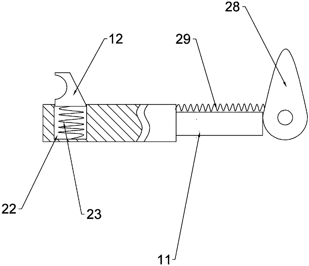
[0023] like image 3 , Figure 4 and Figure 5As shown, the present embodiment also includes a motor and a rotating shaft 15, the motor is fixed on the frame 1, the motor output shaft is connected with the rotating shaft 15, the rotating shaft 15 is provided with a first cam 28 and a second cam 16, the first cam 28 and The second cam 16 does not coincide. An elastic telescopic rod 14 is arranged at the right end of the sliding clamping plate 11 , and the elastic telescopic rod 14 abuts against the first cam 28 . A first spring 29 is provided between the right end of the sliding clamping plate 11 and the frame 1 . The elastic coefficient of the first spring 29 is smaller than that of the elastic telescopic rod 14 . A rack 17 is slidably connected to the frame 1, and a gear 20 is rotatably connected to the frame 1. The gear 20 meshes with the rack 17, the cam offsets the rack 17, and a spring is arranged between the rack 17 and the frame 1. The gear 20 Coaxially is provided...


PUM


Abstract

The invention belongs to the field of automobile accessory machining devices, and particularly discloses an automobile accessory cutting and chamfering device. The automobile accessory cutting and chamfering device comprises a machine frame and a torsion spring, and a feeding mechanism is arranged at one end of the machine frame; a cutting mechanism is arranged on the machine frame, a dropping channel is formed below the cutting mechanism, a discharging port which only allows a single automobile accessory to pass is formed below the dropping channel, a baffle is hinged to the discharging port,and the baffle is connected with the dropping channel through the torsional spring; a clamping mechanism is arranged below the dropping channel, the clamping mechanism comprises a fixed clamping plate and a sliding clamping plate, the sliding clamping plate is in sliding connection with the machine frame, and the fixed clamping plate cooperates with the sliding clamping plate so as to clamp the automobile accessory; and the side part of the fixed clamping plate is provided with a chamfering mechanism, the chamfering mechanism is in sliding connection with the machine frame, and the sliding direction of the chamfering mechanism is perpendicular to the moving direction of the sliding clamping plate. According to the automobile accessory cutting and chamfering device, automatic chamfering can be realized after the automobile accessory is cut, and the working efficiency is improved.

Description

technical field [0001] The invention relates to the field of auto parts processing devices, in particular to a cutting and chamfering device for auto parts. Background technique [0002] Along with the advancement of science and technology and the development of economy, the use of automobiles, especially cars, is becoming more and more common, and people's dependence on automobiles is also increasing when traveling. Therefore, the current automobile industry is developing rapidly, and it has driven the development of related industries, such as the auto parts industry. According to their performance, auto parts can be divided into engine parts, transmission parts, brake parts, steering parts, walking parts, etc., and according to the shape, they can be divided into plate parts, tubular parts, etc. For tubular auto parts In terms of processing, a long auto part is first cut to the required length, and then chamfered. The traditional processing method generally divides a lo...

Claims


Application Information

Patent Timeline
IPC IPC(8): B23P23/02B23Q7/00
CPCB23P23/02B23Q7/00
Inventor 张娜青
Owner 重庆辉海科技有限公司
Why Eureka
Try Eureka