Automatic chamfering machine for coil rod material head

A technology of chamfering machine and wire rod is applied in the field of chamfering machine to achieve the effect of saving feeding time, reducing labor intensity and simple structure

Inactive Publication Date: 2018-02-02
DONGFENG MOTOR FASTENER CO LTD
View PDF0 Cites 0 Cited by
  • Summary
  • Abstract
  • Description
  • Claims
  • Application Information

AI Technical Summary

Problems solved by technology

[0004] The invention provides an automatic chamfering machine for round wire material heads, which solves the problem of manually removing burrs and improves work efficiency

Method used


Image

  • Automatic chamfering machine for coil rod material head
  • Automatic chamfering machine for coil rod material head

Examples


Embodiment Construction

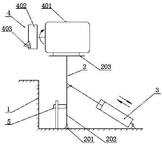
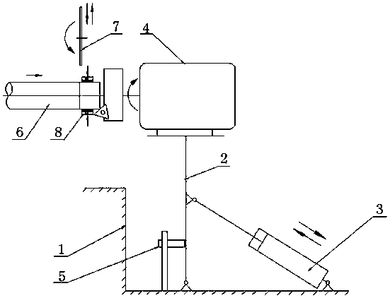
[0011] Such as figure 1 As shown, an automatic chamfering machine for round wire material head includes a frame 1, a support seat 2, a cylinder 3, a chamfering device 4 and a sensor 5; the frame 1 is welded by a plurality of square tubes, fixed on the On the discharge end of the horizontal material rack; the support seat 2 is composed of a bearing seat 201, a vertical rod 202, and a base plate 203. The rotating shaft is connected, the upper end of the vertical rod 202 is connected with the base plate 203, and the vertical rod 202 can rotate around the bearing seat 201; the working table of the frame 1 is provided with a cylinder seat, and the connection end of the cylinder 3 is hinged with the cylinder seat through a pin shaft, thereby realizing The cylinder 3 is hinged on the frame 1; the piston rod in the cylinder 3 is hinged with the middle section of the vertical rod 202 through a pin; the cylinder 3 is manually controlled by a manual valve; Structure; the reducer 401 is ...


PUM

PropertyMeasurementUnit
diameteraaaaaaaaaa

Abstract

An automatic chamfering machine for a round wire material head, including a frame, a support seat, a cylinder, a chamfering device and a sensor, the support seat is composed of a bearing seat, a vertical rod, and a bottom plate, and the bearing seat is arranged on the working table of the frame. One end of the vertical rod is connected to the rotating shaft in the bearing seat, and the other end of the vertical rod is connected to the bottom plate; the connecting end of the cylinder is hinged to the frame, and the piston rod in the cylinder is hinged to the middle section of the vertical rod; the chamfering device is installed in the support seat On the base plate, the chamfering part of the chamfering device faces the forward direction of the support base; the sensor is arranged on the frame, and the sensor is used to limit the rotation angle of the support base; when in use, the support base lifts the chamfering device to the cutting position through the cylinder position, the cutting edge of the blade on the chamfering device contacts the outer circle of the wire material head and cuts the chamfer. The invention realizes the automation of chamfering, replaces the way of manual file repairing, greatly reduces the labor intensity of workers; the operating rate of the equipment is increased by 2.1%, thereby improving the production efficiency.

Description

technical field [0001] The invention relates to a chamfering machine, in particular to an automatic chamfering machine for round wire material heads. Background technique [0002] In the fastener industry, most of the large-scale cold forming equipment adopts coiled wire, and the front end of the main machine of the equipment needs to be equipped with an uncoiling horizontal material rack to facilitate the automatic uncoiling and straightening of the material; because the end surface of the coiled wire material is not flat enough, it cannot be directly It is fed into the main machine of the equipment, so there is also a cutting head of the grinding wheel cutting machine at the front end of the uncoiling horizontal material rack to achieve the purpose of flattening the end surface. The section after cutting by the grinding wheel will produce burrs or burrs, which is not convenient for the material to be transported to the main machine of the equipment for cutting. In the die ...

Claims


Application Information

Patent Timeline
Patent Type & Authority Applications(China)
IPC IPC(8): B21F11/00
CPCB21F11/00
Inventor 唐志文刘征邹汉涛
Owner DONGFENG MOTOR FASTENER CO LTD
Why Eureka
Try Eureka