Production equipment and production process for chamfering pin

A technology of production equipment and production process, which is applied in the field of production equipment and production technology with chamfered pins, and can solve problems such as unreasonable production process of pins, low production efficiency of pins, and inability to meet the needs of actual production. , to achieve the effects of improving manufacturing efficiency, realizing automated manufacturing, and optimizing manufacturing processes

Pending Publication Date: 2020-06-09
东莞市群桦精密五金有限公司
View PDF0 Cites 0 Cited by
  • Summary
  • Abstract
  • Description
  • Claims
  • Application Information

AI Technical Summary

Problems solved by technology

[0002] In the manufacturing process of the pins, on the one hand, the pins need to be bent, and on the other hand, the pins need to be chamfered. In the prior art, the blanks of the pins are mainly manufactured first, and then the single The pin blanks are bent and chamfered. Due to the unreasonable manufacturing process of the pins, the production efficiency of the pins is low and cannot meet the needs of actual production.

Method used


Image

  • Production equipment and production process for chamfering pin
  • Production equipment and production process for chamfering pin
  • Production equipment and production process for chamfering pin

Examples


Embodiment Construction

[0031] The present invention will be further described below with reference to the embodiments and the accompanying drawings.

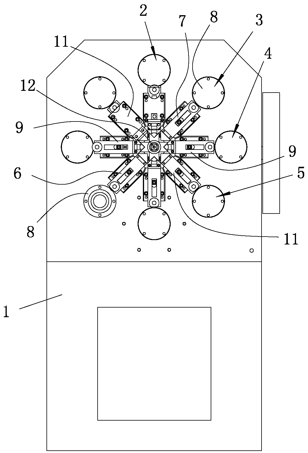
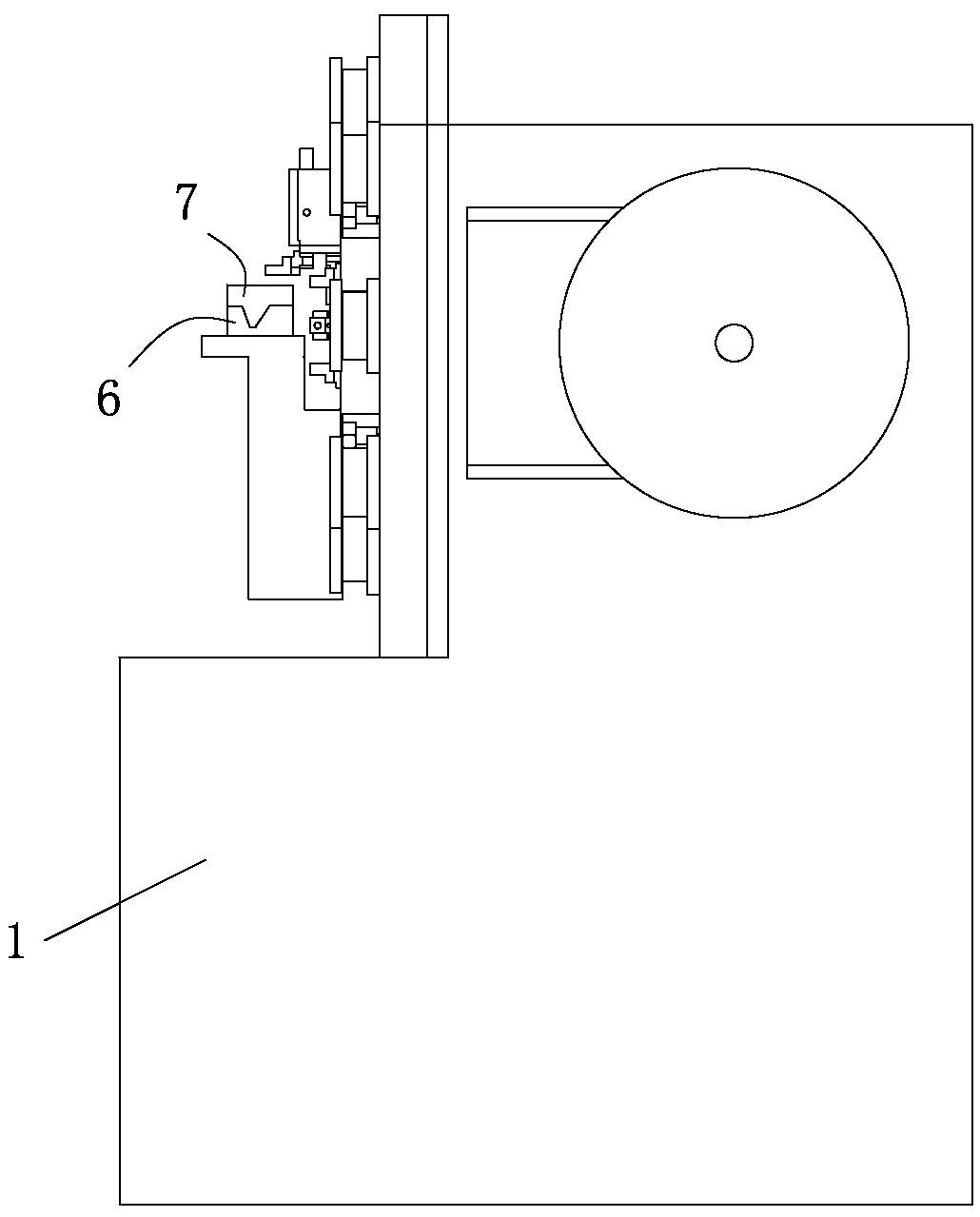
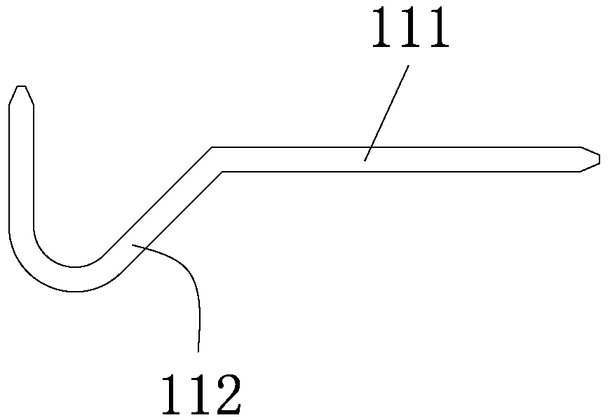
[0032] refer to Figure 1-Figure 3 , A production equipment with chamfered pins of the present invention includes a machine 1, a conveying mechanism 2, a forming mechanism 3, a chamfering mechanism 4 and a cutting mechanism 5 installed and arranged on the machine 1. The conveying mechanism 2 is used for Drive the external bar material to move, the bar material is straight, and the conveying mechanism 2 drives the bar material to move automatically; the forming mechanism 3 includes a relatively close or far away die 6 and a punch 7. The punch 6 and the punch 7 cooperate with each other so as to A bending part 112 is formed on the bar conveyed by the conveying mechanism 2, and the bending part 112 is roughly V-shaped. Of course, the bending part 112 can also be C-shaped, U-shaped or W-shaped; the chamfering mechanism 4 is forming Chamfering is performe...


PUM


Abstract

The invention relates to the technical field of pin manufacturing and particularly discloses production equipment and production process for a chamfering pin. The production equipment comprises a machine table, a conveying mechanism, a forming mechanism, a chamfering mechanism and a cutting mechanism, wherein the conveying mechanism, the forming mechanism, the chamfering mechanism and the cuttingmechanism are arranged on the machine table. The conveying mechanism is used for driving an external bar material to move. The forming mechanism comprises a female die and a male die which are relatively close to or far away from each other. The female die and the male die are matched to realize bending portion forming on the bar material conveyed by the conveying mechanism. The chamfering mechanism performs chamfering treatment on the bar material processed by the forming mechanism, so that a chamfering part is formed on the bar material. The cutting mechanism cuts off the bar material at thechamfering part processed by the chamfering mechanism, and the chamfering pin is formed. The conveying mechanism realizes the automatic conveying of the bar material. The forming mechanism realizes the automatic forming of the bar material. The chamfering mechanism realizes the automatic chamfering of the bar material. The cutting mechanism realizes automatic cutting of the bar material. Automatic production and manufacturing of the chamfering pin are realized; and the production and manufacturing efficiency of the chamfering pin is improved.

Description

technical field [0001] The invention relates to the technical field of pin manufacturing, and particularly discloses a production equipment and a production process for a pin with a chamfer. Background technique [0002] In the manufacturing process of the pin, on the one hand, the pin needs to be bent, and on the other hand, the pin needs to be chamfered. In the prior art, the pin blank is mainly manufactured first, and then the single pin The pin blank is bent and chamfered. Due to the unreasonable manufacturing process of the pin, the production efficiency of the pin is low and cannot meet the needs of actual production. SUMMARY OF THE INVENTION [0003] In order to overcome the shortcomings and deficiencies in the prior art, the purpose of the present invention is to provide a production equipment with chamfered pins, realize automatic production and manufacture of chamfered pins, and improve the production efficiency of chamfered pins . [0004] In order to achieve ...

Claims


Application Information

Patent Timeline
Patent Type & Authority Applications(China)
IPC IPC(8): B23P23/06
CPCB23P23/06
Inventor 尧章华
Owner 东莞市群桦精密五金有限公司
Why Eureka
Try Eureka