Soldering iron head production process

A production process and soldering iron tip technology, applied in soldering irons, manufacturing tools, metal processing equipment, etc., can solve problems such as damage to human health, unstable quality, and sewage discharge, saving labor, default processes, and short production cycles Effect

Active Publication Date: 2018-01-02
陈爱华
View PDF5 Cites 0 Cited by
  • Summary
  • Abstract
  • Description
  • Claims
  • Application Information

AI Technical Summary

Problems solved by technology

[0004] The invention provides a soldering iron tip production process, which aims to improve the existing soldering iron tip production process. The process of using an electroplated iron layer will discharge sewage, and the high-temperature steam of the electroplating solution will seriously volatilize and pollute the environment, damaging human health and processing. The problem of large deviation and unstable quality

Method used


Image

  • Soldering iron head production process
  • Soldering iron head production process
  • Soldering iron head production process

Examples


Embodiment 1

[0053]Embodiment 1 of the present invention provides a soldering iron tip production process, the soldering iron tip production process comprises:

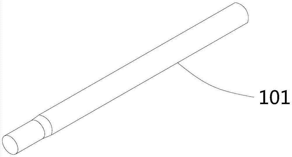
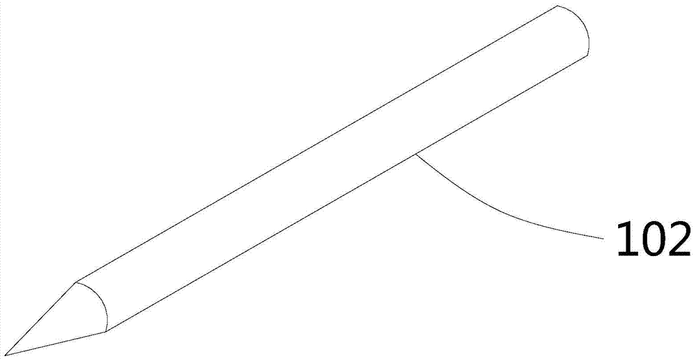
[0054] Copper mold blank 102 manufacturing steps: Copper raw material is made into copper blank 101, and one end thereof is processed into a tapered working end.

[0055] Copper billet iron sleeve fitting 104 processing steps:

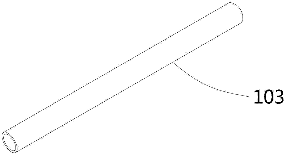
[0056] The iron sleeve 103 is placed outside the copper mold blank 102 and fixed to form a copper blank iron sleeve 104 .

[0057] A die is used to process one end of the iron sleeve 103 into a tapered shape that completely covers the working end of the copper mold blank 102 to form the head of the copper blank iron sleeve 104 .

[0058] Dimensional correction step: carry out dimensional correction to the body of the copper billet iron casing 104 to reach the standard size.

[0059] Surface treatment step: surface treatment is carried out on the copper billet iron casing piece 104 .

[0060] Thus, a sol...

Embodiment 2

[0063] Embodiment 2 of the present invention provides a soldering iron tip production process, the soldering iron tip production process includes all the technical features of the soldering iron tip production process provided in Embodiment 1, and the process steps of the soldering iron tip production process are as follows:

[0064] Manufacturing steps of the copper mold blank 102: straighten, position, and cut the copper disc material according to the product size requirements, and extrude it into a copper billet 101. For the structure of the copper billet 101, please refer to figure 1 . The size of the copper billet 101 is generally φ3.5mm-φ9.0mm, and the length is generally 35mm-100mm. This embodiment takes φ5.2mm and length 69mm as an example for specific description. Then utilize a lathe to turn one end of the copper blank 101 into a tapered shape, and turn the other end of the copper blank 101 into a chamfered position to form a copper mold blank 102. For the structure...

Embodiment 3

[0092] Embodiment 3 of the present invention provides a production process of a soldering iron tip. The difference between the production process of the soldering iron tip and the production process of the soldering iron tip provided in Embodiment 2 is that:

[0093] The production process of the soldering iron tip provided in Embodiment 3 also includes a forming step, which is after the processing step of the copper billet iron sleeve 104, specifically, the forming step is after the dimension correction step.

[0094] Forming step: process the head into a horseshoe shape, a knife edge shape or a flat mouth shape. What the present embodiment adopts is that mechanical extrusion process is pressed the head into horseshoe shape, knife-edge shape or flat mouth shape.

[0095] It should be understood that after the size correction step, the body is already a straight cylindrical shape, and the head is processed into a horseshoe shape, a knife-edge shape or a flat mouth shape, so wh...


PUM

PropertyMeasurementUnit
lengthaaaaaaaaaa
lengthaaaaaaaaaa

Abstract

The invention provides a solder tip production process and belongs to the technical field of solder tip production. The solder tip production process comprises the following steps: a step of manufacturing a copper mould blank: manufacturing a copper blank from a copper raw material and processing one end of the copper blank to a cone-shaped work end; a step of processing a copper blank and iron sleeve: sleeving a copper mould blank by an iron sleeve and fixing the iron sleeve to form the copper blank and iron sleeve; processing one end of the iron sleeve through a die to a cone shape, wherein the work end of the copper mould blank is fully coated so as to form the head of the copper blank and iron sleeve; a step of correcting the dimension: correcting the dimension of the body of the copper bank and iron sleeve to meet the standard dimension; a step of surface treatment: carrying out surface treatment on the copper blank and iron sleeve. The solder tip production process provided by the invention adopts a machine assembling and processing process of embedding the copper blank into the iron sleeve to replace a process of electroplating an iron layer, is free of discharge of electroplating sewage and environmental pollution and is environmental-friendly; the dimensions of workpieces are accurate and uniform, so that the workpieces can be automatically produced and manufactured, and the product is stable in quality and short in production period.

Description

technical field [0001] The invention relates to the technical field of soldering iron tip production, in particular to a soldering iron tip production process. Background technique [0002] Soldering iron tips (also known as solder tips) are commonly used for heating and welding in the production of circuit boards and electrical appliances in the electronics industry. The soldering iron head generally includes a head and a body. The shape of the head is various, generally conical, horseshoe-shaped, flat-shaped, knife-edge, etc., and the body is generally straight cylindrical or stepped. [0003] The existing soldering iron tip production process is usually to use a lathe to turn the copper billet, turn the head into a tapered shape, then polish the surface of the copper billet and then electroplate the iron layer, and then through machine tool grinding and lathe turning, so that the head and The body reaches the size standard, and then the subsequent processing is carried o...

Claims


Application Information

Patent Timeline
Patent Type & Authority Patents(China)
IPC IPC(8): B23P15/00B23K3/02
CPCB23K3/025B23P15/00
Inventor 陈爱华
Owner 陈爱华
Why Eureka
Try Eureka