Die with ejection needle on sliding block

A technology of thimble and slider, which is applied in the field of plastic molds, and can solve problems such as the inability to realize fully automatic production, the removal of the glue inlet, and the inability to demould

Pending Publication Date: 2018-11-13
林宝梁
View PDF4 Cites 1 Cited by
  • Summary
  • Abstract
  • Description
  • Claims
  • Application Information

AI Technical Summary

Problems solved by technology

[0002] After the injection molding of the product is completed, the top, bottom, left, right and front of the entire product are appearance surfaces. The appearance requirements of the product are extremely strict, and it is not allowed to leave any traces of the plastic inlet on the appearance surface of the product, so only The glue inlet can be designed in the depression at the back of the product. However, the depression is located in the middle of the back. To feed glue in the depression, only submerged feeding can be used. The existing submerged feeding method must be equipped with a thimble The demoulding can only be done after ejection. If the ejector pin is not designed, the demoulding cannot be carried out, and automatic production cannot be realized. After the injection molding is completed, the glue inlet cannot be directly taken out by the robot.

Method used


Image

  • Die with ejection needle on sliding block
  • Die with ejection needle on sliding block

Examples


Embodiment Construction

[0014] In order to make the purpose, technical solutions and advantages of the embodiments of the present invention clearer, the technical solutions in the embodiments of the present invention will be clearly and completely described below in conjunction with the drawings in the embodiments of the present invention. Obviously, the described embodiments It is a part of embodiments of the present invention, but not all embodiments. Based on the embodiments of the present invention, all other embodiments obtained by persons of ordinary skill in the art without creative efforts fall within the protection scope of the present invention.

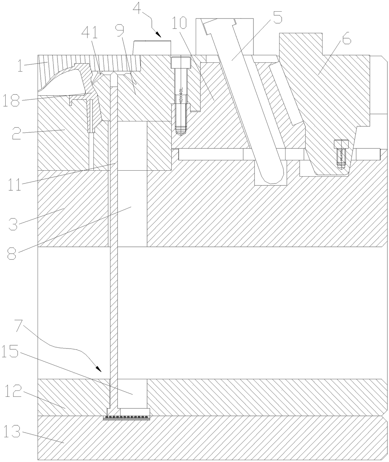
[0015] Please refer to figure 1 , the embodiment of the present invention provides a mold equipped with a thimble on the slider, including a front mold core 1, a rear mold core 2, a rear template 3, a slider assembly 4, an oblique pin 5, an oblique pressure block 6 and an thimble Assembly 7, the front mold core 1 and the rear mold core 2 are encl...


PUM


Abstract

The invention discloses a die with an ejection needle on a sliding block. The die comprises a front die core, a back die core, a back die plate, a sliding block assembly, an oblique pin and an ejection needle assembly; the front end of the sliding block assembly is provided with a feeding port; the ejection needle assembly is inserted into the back die plate, the back die core and the sliding block assembly sequentially from bottom to top and makes contact with the feeding port arranged on the sliding block assembly in a matching mode, the ejection needle assembly can vertically slide relativeto the back die core, the back die plate and the sliding block assembly, and first sliding grooves used for allowing the ejection needle assembly to move front and back are formed in the back die core and the back die plate; and the oblique pin is inserted into the back end of the interior of the sliding block assembly, the back die plate walks to drive the oblique pin to swing, then the slidingblock assembly is driven to move front and back, and the ejection needle assembly is driven to move front and back in the first sliding grooves. According to the die with the ejection needle on the sliding block, the structure is simple, full-automatic production of submersing type feeding is achieved, it is effectively guaranteed that a glue inlet of a product is formed in the sunken portion ofthe product, product appearance perfection is guaranteed, and the strict requirements of people on the product appearance are met.

Description

technical field [0001] The present invention and the technical field of plastic molds, more specifically, relate to a mold with a thimble mounted on a slider. Background technique [0002] After the injection molding of the product is completed, the top, bottom, left, right and front of the entire product are appearance surfaces. The appearance requirements of the product are extremely strict, and it is not allowed to leave any traces of the plastic inlet on the appearance surface of the product, so only The glue inlet can be designed in the depression at the back of the product. However, the depression is located in the middle of the back. To feed glue in the depression, only submerged feeding can be used. The existing submerged feeding method must be equipped with a thimble If the ejector pin is not designed, the demoulding cannot be performed, and fully automatic production cannot be realized. After the injection molding is completed, the glue inlet cannot be directly tak...

Claims


Application Information

Patent Timeline
Patent Type & Authority Applications(China)
IPC IPC(8): B29C45/33B29C45/40
CPCB29C45/332B29C45/4005
Inventor 林宝梁
Owner 林宝梁
Why Eureka
Try Eureka