Plastic pipe sizing and cooling production device

A production device and technology for plastic pipes, applied in the field of plastic pipe manufacturing, can solve problems that affect production smoothness, product quality and yield, product standards that do not meet the requirements for use, and poor shaping ability, so as to improve quality and yield, Uniform cooling and small site space

Active Publication Date: 2018-11-13
SICHUAN NIGALE BIOTECH
View PDF6 Cites 0 Cited by
  • Summary
  • Abstract
  • Description
  • Claims
  • Application Information

AI Technical Summary

Problems solved by technology

[0002] At present, some raw materials in the production workshop of plastic pipes have the characteristics of strong fluidity and poor setting ability after high-temperature plasticization.
When these materials are used to produce plastic pipes, they will stick and deform at high temperatures. Although they are hard after being cooled by the current cooling process and equipment, most of them do not meet the requirements for use and related product standards, seriously affecting the smooth production and products. Quality and Yield

Method used


Image

  • Plastic pipe sizing and cooling production device
  • Plastic pipe sizing and cooling production device
  • Plastic pipe sizing and cooling production device

Examples


Embodiment 1

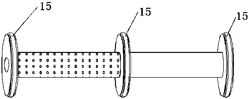
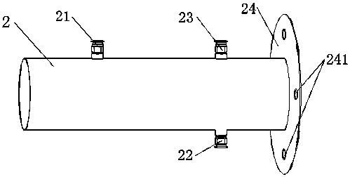
[0023] Plastic pipe sizing and cooling production device, including copper circular sizing core (1), stainless steel circular sizing shell (2), circular sizing core (1) including the inlet and outlet of the plastic pipe, in The two ends and the middle of the circular sizing inner core (1) are respectively fixed with an inlet sealing end plate (11), an outlet sealing end plate (12) and a boundary sealing plate (13); the inlet sealing end plate ( 11), the outer edges of the outlet sealing end plate (12) and the boundary sealing plate (13) are provided with ring-mounted sealing strips; the two ends of the circular sizing core (1) and the circular sizing shell (2) are flush, and The circular sizing core (1) is concentrically sealed and fixed in the inner chamber of the circular sizing shell (2) in a detachable manner.

[0024] The sizing zone is between the inlet sealing end plate (11) and the boundary sealing plate (13), and the preliminary cooling zone is between the outlet seal...

Embodiment 2

[0028] The difference between this embodiment and Embodiment 1 is that the circular sizing inner core (1) and the circular sizing shell (2) are made of copper, and the inlet sealing end plate (11) and the outlet sealing end plate (12) The circular sizing inner core (1) and the circular sizing shell (2) are connected and fixed by welding with the boundary sealing plate (13). In the primary cooling area between the outlet sealing end plate (12) and the boundary sealing plate (13), 2 split sealing plates (not shown in the drawings) are added to divide the primary cooling area into 3 secondary cooling areas. The shape and material of the sealing plate and the boundary sealing plate (13) are the same, and the connection and fixing method of the circular sizing inner core (1) and the circular sizing shell (2) is also the same. Water inlets (22) and water outlets (23) are provided on the circular sizing shells (2) to which the three secondary cooling zones belong. The difference fro...

Embodiment 3

[0030] The difference between this embodiment and embodiment 1 is that in embodiment 1, a split sealing plate is added, that is, the split sealing plate is welded on the circular sizing inner core (1) of the preliminary cooling zone, and the split sealing plate and the boundary sealing plate ( 13) The shape and material remain the same, and the same ring-mounted sealing strips are provided on the edges of the split sealing plate and the boundary sealing plate (13).


PUM


Abstract

The invention provides a plastic pipe sizing and cooling production device. The plastic pipe sizing and cooling production device comprises a circular sizing inner core and a circular sizing outer shell, wherein the circular sizing inner core comprises an inlet and an outlet of a plastic pipe and is concentrically fixed in an inner cavity of the circular sizing outer shell, the two ends of the circular sizing inner core are flush with the two ends of the circular sizing outer shell, an annular space between the circular sizing inner core and the circular sizing outer shell is generally dividedinto a sizing area and a primary cooling area, the sizing area is used for sizing the plastic pipe, and the primary cooling area is used for rapidly cooling the plastic pipe. According to the plasticpipe sizing and cooling production device, the sizing area and the cooling area are integrally designed, so that the plastic pipe sizing and cooling production device is more intensive, the occupiedfield space is smaller, assembly, disassembly and the like are more convenient, the deformation degree of the plastic pipe after extrusion can be controlled, then the plastic pipe can be cooled more uniformly, finally, the easy-to-deform pipe body can be controlled to meet the diameter requirement required to be met, and the quality and the yield of the product are greatly improved.

Description

technical field [0001] The invention belongs to the field of plastic pipe manufacturing, in particular to a plastic pipe sizing and cooling production device for sizing and cooling plastic pipe fittings. Background technique [0002] At present, some raw materials in the production workshop of plastic pipes have the characteristics of strong fluidity and poor setting ability after high-temperature plasticization. When these materials are used to produce plastic pipes, they will stick and deform at high temperatures. Although they are hard after being cooled by the current cooling process and equipment, most of them do not meet the requirements for use and related product standards, seriously affecting production and products. Quality and Yield. Contents of the invention [0003] The purpose of the present invention is to solve the above-mentioned problems, to provide a method that can control the degree of deformation of the plastic pipe after extrusion, make it cool more...

Claims


Application Information

Patent Timeline
Patent Type & Authority Applications(China)
IPC IPC(8): B29C47/88B29L23/00
CPCB29L2023/22
Inventor 杨世川
Owner SICHUAN NIGALE BIOTECH
Why Eureka
Try Eureka