Control console used for material receiving machine

A technology of consoles and splicers, applied in the direction of conveyor control devices, conveyor objects, transportation and packaging, etc., can solve the problems of production line shutdown efficiency, hidden dangers of personal safety of staff, losses, etc., and achieve the effect of delaying oxidation and corrosion Speed, simplification of the operation process, and the effect of protecting the mechanical device

Inactive Publication Date: 2018-11-13
苏州沸迩灵精密制造有限公司
View PDF5 Cites 0 Cited by
  • Summary
  • Abstract
  • Description
  • Claims
  • Application Information

AI Technical Summary

Problems solved by technology

[0003] However, the length of the material tape is limited, and the production line stops due to the replacement of the material tape during production, resulting in a loss of efficiency
In order to reduce the number of downtimes and time wasted for replacing material belts, the current production enterprises manually connect multiple material belts and stick together multiple material belts, which will consume a lot of labor costs and bring safety hazards to the personal safety of the staff. and low work efficiency
Manual splicing of SMD strips has been unable to meet the industry's requirements for the quantity and quality of strips. It has become a trend to use mechanized and automated splicing of strips instead of manual splicing.
[0004] In the existing material receiving machine, the control surface of the console is generally set horizontally or vertically. When the vertical control surface is operating, the operator needs to squat down to see the content displayed on the control panel; when the control panel is horizontal When setting, the operator has to lower his head to see the content displayed on the control panel clearly. Both of these settings make it inconvenient for the operator to operate the splicer

Method used


Image

  • Control console used for material receiving machine
  • Control console used for material receiving machine

Examples


Embodiment Construction

[0024] The invention will now be further described in detail in conjunction with the accompanying drawings and embodiments. These accompanying drawings are all simplified schematic diagrams, and only illustrate the basic structure of the present invention in a schematic manner, so it only shows the configuration related to the present invention.

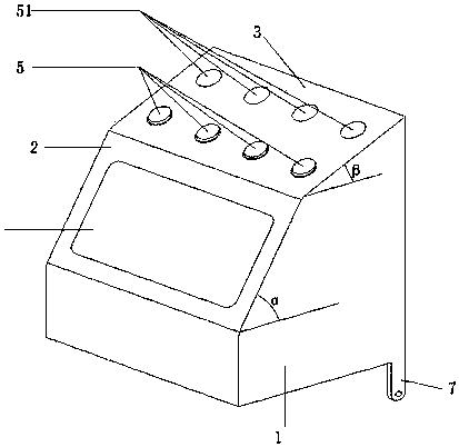
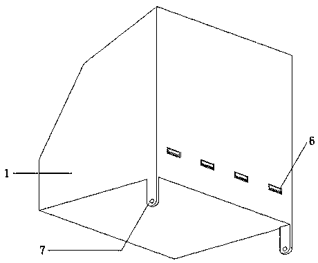
[0025] Such as Figure 1 to Figure 2 As shown, the display plane 2 forms an angle α with the horizontal plane, and the value of the α angle is 40~60°. The button plane 3 is set above the display plane 2. The button plane 3 forms an angle β with the horizontal plane, and the value of the β angle is 15~30°. °. The bottom of the body 1 is provided with a rotating mechanism 7 that can rotate around the fixed shaft of the splicer. The display plane 2 is provided with a display frame 4 . The button plane 3 is provided with a button 5 and a buttonhole 51 reserved for installing the button 5 . The back of the main body 1 is provided with a...


PUM


Abstract

The invention relates to a control console used for a material receiving machine. The control console comprises a body, the body is provided with a display plane and a button plane, and certain anglesare formed between the display plane and the horizontal face and between the button plane and the horizontal face; and a rotating mechanism capable of rotating around a material receiving machine fixing shaft is arranged below the body, buttons and holes reserved for installation of the buttons are installed on the button plane, and the back face of the body is provided with a communication interface exchanging information with the outside. The control console accords with the human body engineering design, an operator can achieve operation of the material receiving machine through fewer motions, and the operation flow is simplified.

Description

technical field [0001] The invention relates to an automatic material receiving device, in particular to a console for the material receiving machine. Background technique [0002] With the development of the electronics industry, surface mount technology is more and more widely used in the manufacturing of electronic products. Surface mount technology is to use SMD devices to realize the continuous assembly and automation of production of electronic products. [0003] However, the length of the material tape is limited, and the production line is shut down due to the replacement of the material tape during production, resulting in a loss of efficiency. In order to reduce the number of downtimes and time wasted for replacing material belts, the current production enterprises manually connect multiple material belts and stick together multiple material belts, which will consume a lot of labor costs and bring safety hazards to the personal safety of the staff. And work effic...

Claims


Application Information

Patent Timeline
Patent Type & Authority Applications(China)
IPC IPC(8): B65G43/00
CPCB65G43/00
Inventor 秦杰刘鹏
Owner 苏州沸迩灵精密制造有限公司
Why Eureka
Try Eureka