Automatic conveying line for keycap transfer printing equipment

An automatic conveying and keycap technology, applied in the direction of conveyors, conveyor objects, transportation and packaging, etc., can solve the problems that cannot be sent to the next station correctly, the impact force of the rotating cylinder is large, and the line body cannot operate normally, etc.

Pending Publication Date: 2018-11-13
林焕城
View PDF8 Cites 16 Cited by
  • Summary
  • Abstract
  • Description
  • Claims
  • Application Information

AI Technical Summary

Problems solved by technology

[0002] The existing keycap pad printing equipment 9 is manually loaded, and the keycaps in the tray are manually turned over and put into the pad printing equipment 9, so that the efficiency is low and safety problems sometimes occur.
[0003] When transporting pallets on the belt line, we often encounter the problem of pallet accumulation. The accumulation of pallets will cause material jams, such as: overlapping up and down in the front and rear directions, misalignment in the left and right directions, etc., which will eventually cause the line body to fail to operate normally; the usual solution: 1. Manually stack Take off the tray, and put the tray back into the line body when the line body is operating normally, this operation takes manpower; 2. Lengthen the belt line to increase the storage capacity of the tray, which will increase the floor area
[0004] The bottom of the keycap, that is, the inner cavity, needs to be pad-printed during pad printing of the keycap, so the keycap on the tray needs to be turned over before pad printing. The flipping mechanism is generally completed by a rotary cylinder, but when the rotary cylinder rotates The impact force is relatively large, and an external buffer limit is required. However, this setting often causes the keycap on the rotating mechanism to be shaken off or shifted, and cannot be sent to the next station correctly.

Method used


Image

  • Automatic conveying line for keycap transfer printing equipment
  • Automatic conveying line for keycap transfer printing equipment
  • Automatic conveying line for keycap transfer printing equipment

Examples


Embodiment Construction

[0036] The following will clearly and completely describe the technical solutions in the embodiments of the present invention. Obviously, the described embodiments are only some of the embodiments of the present invention, rather than all the embodiments. Based on the embodiments of the present invention, all other embodiments obtained by persons of ordinary skill in the art without making creative efforts belong to the protection scope of the present invention.

[0037] see Figure 1 to Figure 17 , the embodiment of the present invention includes:

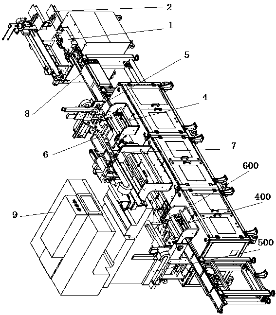
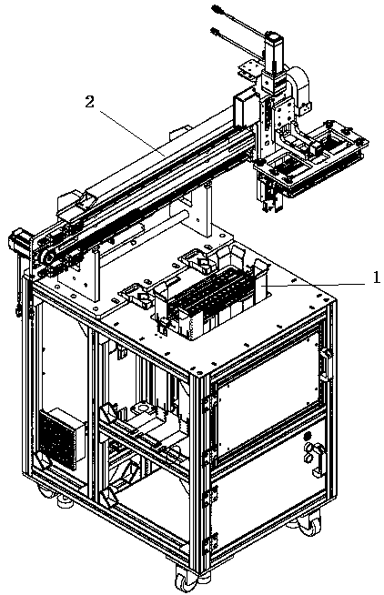
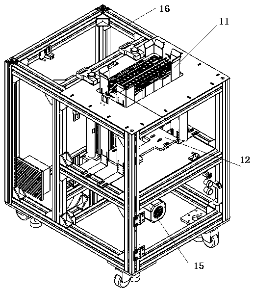
[0038] Automatic conveying line for pad printing keycap equipment, including: tray lifting and temporary storage mechanism 1, tray transfer manipulator 2, feeding lifting positioning mechanism 3, feeding turning and transferring mechanism 4, feeding and transferring module 5, feeding Reciprocating transfer module 6, double transfer equipment 7, unloading reciprocating transfer module 600, unloading transfer module 500, unloading ...


PUM


Abstract

The invention discloses an automatic conveying line for keycap transfer printing equipment. The automatic conveying line for the keycap transfer printing equipment comprises a tray lifting and temporary storing mechanism, a tray transferring and loading manipulator, a feeding, lifting and positioning mechanism, a feeding, turning-over, transferring and loading mechanism, a feeding, transferring and loading module, a feeding and reciprocated transferring and loading module, dual transferring and loading equipment, a discharging and reciprocated transferring and loading module, a discharging, transferring and loading module, a discharging, turning-over, transferring and loading mechanism, and a discharging, lifting and positioning mechanism. Through the manner, according to the automatic conveying line for the keycap transfer printing equipment provided by the invention, the automatic conveying line for the transfer printing equipment is directly connected with the last process for keycap processing, trays are conveyed by utilizing the conveying line, and the turning-over, transferring and loading mechanisms are arranged on a line body, so that conveyed keycaps can be turned over; and in addition, the transferring and loading manipulator on the conveying line body can feed the turned-over keycaps into the transfer printing equipment, and meanwhile, the conveying line body furthercomprises the temporary storing mechanism for temporarily conveying the trays for the keycaps, so that automatic feeding and discharging of transfer printing can be realized without the need for manual intervention, the cost is saved, the efficiency is improved, and the accuracy is high.

Description

technical field [0001] The invention relates to the field of automation equipment, in particular to an automatic conveying line for pad printing keycap equipment. Background technique [0002] The existing keycap pad printing equipment 9 is manually loaded, and the keycaps in the tray are manually turned over and put into the pad printing equipment 9, so that the efficiency is low and safety problems sometimes occur. [0003] When transporting pallets on the belt line, we often encounter the problem of pallet accumulation. The accumulation of pallets will cause material jams, such as: overlapping up and down in the front and rear directions, misalignment in the left and right directions, etc., which will eventually cause the line body to fail to operate normally; the usual solution: 1. Manually stack Take off the tray, and put the tray back into the line body when the line body is operating normally, this operation takes manpower; 2. Lengthen the belt line to increase the st...

Claims


Application Information

Patent Timeline
Patent Type & Authority Applications(China)
IPC IPC(8): B65G47/74B65G47/248B65G47/91
CPCB65G47/248B65G47/74B65G47/91B65G2201/0258
Inventor 林焕城
Owner 林焕城
Why Eureka
Try Eureka