Small-scale copper wire winding mechanism capable of moving leftwards and rightwards

A winding mechanism, left and right technology, applied in the direction of conveying filamentous materials, thin material processing, transportation and packaging, etc., can solve the problems of fixed movement troubles, fixed limit positions, and inability to meet small cylinder winding use, etc. To achieve the effect of guaranteed winding effect, convenient installation and disassembly

Inactive Publication Date: 2018-11-13
FOSHAN XUNTUOAO TECH CO LTD
View PDF0 Cites 9 Cited by
  • Summary
  • Abstract
  • Description
  • Claims
  • Application Information

AI Technical Summary

Problems solved by technology

[0002] The existing thin copper wire is generally wound by a small cylinder, and its winding mechanism is relatively small. It uses two thimbles for clamping and fixing, and the fixing plate of the thimble on one side can be moved to realize the small cylinder. The installation and disassembly of the body, and the movement of the fixed plate is generally manually moved and fixed by bolts. The fixed movement is troublesome and the effect is not ideal; and when winding, the copper wire of the large cylinder is generally wound into the small cylinder When winding, the small cylinder needs to move laterally left and right according to the amount of copper wire coming from the large cylinder, so as to ensure that the copper wire moves laterally along the small cylinder to ensure the winding effect. Among them, the lateral movement of the small cylinder requires To limit the position, the existing limit is to fix the limit block or the limit switch on the support plate at both ends of the horizontal screw to limit the position. The position of the limit is fixed and cannot be adjusted according to the needs. body winding use

Method used


Image

  • Small-scale copper wire winding mechanism capable of moving leftwards and rightwards
  • Small-scale copper wire winding mechanism capable of moving leftwards and rightwards
  • Small-scale copper wire winding mechanism capable of moving leftwards and rightwards

Examples


Embodiment

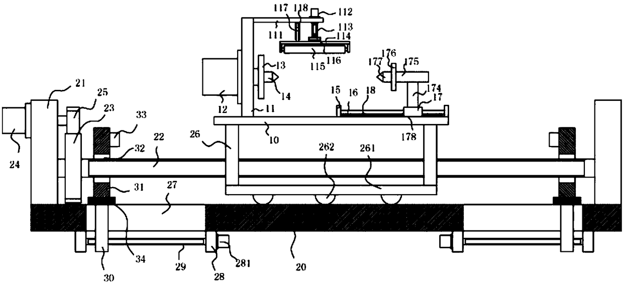
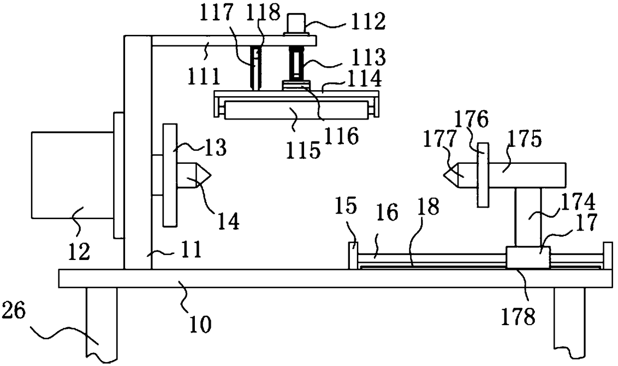
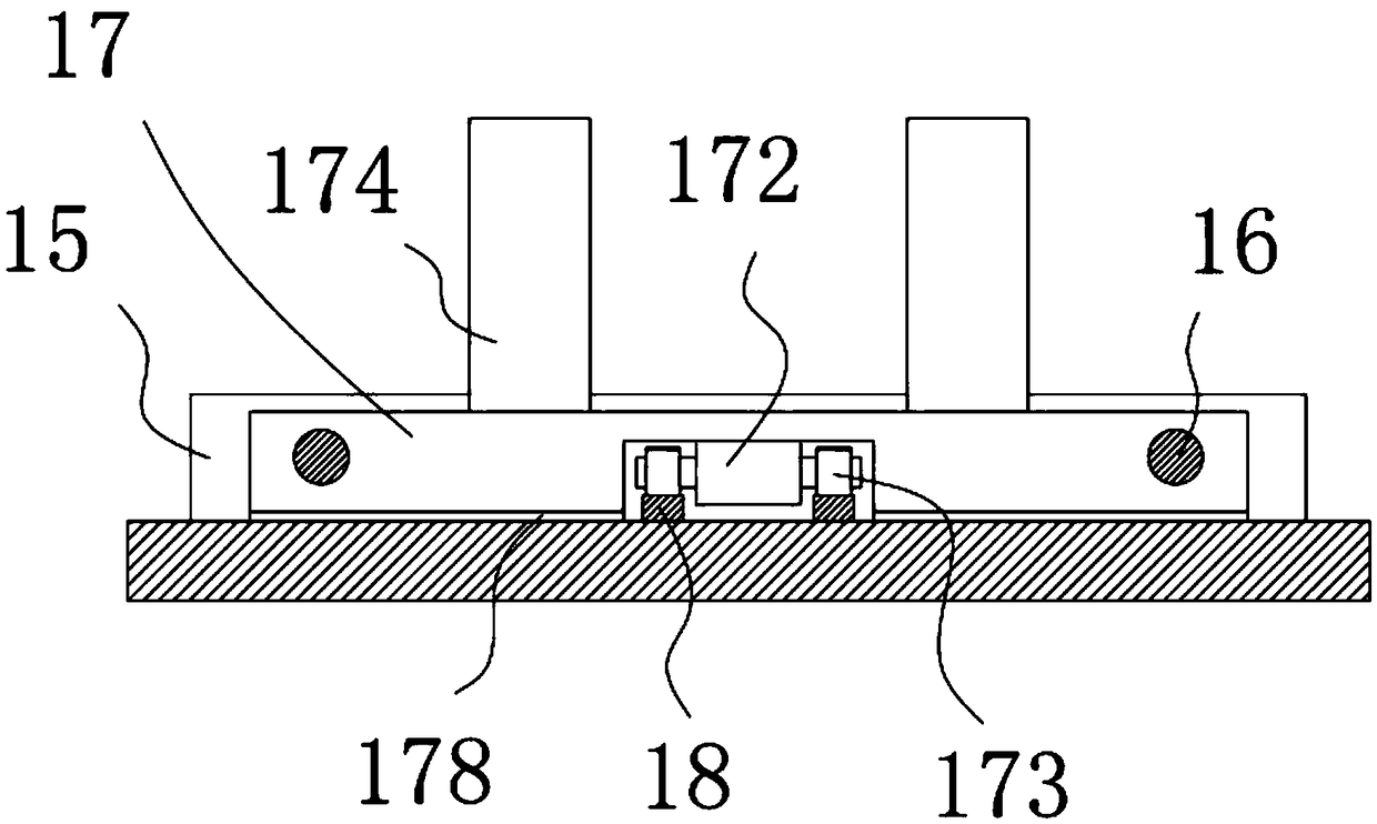
[0022] Example: see Figure 1 to Figure 3 As shown, a left and right movable small-sized copper wire winding mechanism includes a main base plate 10 and a support bracket 20, side support plates 21 are fixed on the top surfaces of the left and right sides of the base plate of the support bracket 20, and the main transverse screw rod 22 The two ends of the two side support plates are hinged on the two side support plates 21 through bearings. One end of the main transverse screw rod 22 is fixed with a mobile transmission gear 23, and the outer wall of the side support plate 21 is fixed with a main mobile motor 24. The output shaft of the main mobile motor 24 Pass through the side support plate 21 and be fixed with a mobile drive gear 25, the mobile drive gear 25 is meshed with the mobile transmission gear 23, the bottom surface of the main base plate 10 is fixed with two lower vertical plates 26, and the two lower vertical plates 26 are screwed together. In the main transverse s...


PUM


Abstract

The invention discloses a small-scale copper wire winding mechanism capable of moving leftwards and rightwards. The small-scale copper wire winding mechanism capable of moving leftwards and rightwardscomprises a main base plate and a supporting and fixing frame. Side supporting plates are fixed to the top faces of the left side and the right side of the base plate of the supporting and fixing frame. The two ends of a main transverse screw are hinged to the two side supporting plates through bearings. A movable transmission gear is fixed to one end of the main transverse screw. A main movablemotor is fixed to the outer side wall of one side supporting plate. The output shaft of the main movable motor penetrates through the corresponding side supporting plate, and a movable driving gear isfixed to the output shaft of the main movable motor. The movable driving gear is meshed with the movable transmission gear. Two lower vertical plates are fixed to the bottom face of the main base plate. The two lower vertical plates are in threaded connection with the main transverse screw. A vertical supporting plate is fixed to the top face of the left side of the main base plate. A rotary servo motor is fixed to the left side wall of the vertical supporting plate. A movable block in the position of a right ejector pin of the winding mechanism can move leftwards and rightwards automatically, and thus a small barrel body for winding is mounted and disassembled conveniently. Besides, positions of two limiting plates can be adjusted automatically, and thus positions of two proximity switches are adjusted.

Description

technical field [0001] The invention relates to the technical field of metal wire processing equipment, in particular to a left and right movable small copper wire winding mechanism. Background technique [0002] The existing thin copper wire is generally wound by a small cylinder, and its winding mechanism is relatively small. It uses two thimbles for clamping and fixing, and the fixing plate of the thimble on one side can be moved to realize the small cylinder. The installation and disassembly of the body, and the movement of the fixed plate is generally manually moved and fixed by bolts. The fixed movement is troublesome and the effect is not ideal; and when winding, the copper wire of the large cylinder is generally wound into the small cylinder When winding, the small cylinder needs to move laterally left and right according to the amount of copper wire coming from the large cylinder, so as to ensure that the copper wire moves laterally along the small cylinder to ensur...

Claims


Application Information

Patent Timeline
Patent Type & Authority Applications(China)
IPC IPC(8): B65H54/553B65H54/44B65H54/52B65H54/28
CPCB65H54/553B65H54/2803B65H54/44B65H54/52B65H2701/36
Inventor 叶侃
Owner FOSHAN XUNTUOAO TECH CO LTD
Why Eureka
Try Eureka