Double buoyancy ball overflow preventing floor drain

A buoyancy ball and anti-backflow technology, which is applied to waterway systems, drainage structures, water supply devices, etc., can solve the problems of drying up, less sealing water, and odor return, and achieve good effect, long water sealing time, and convenient cleaning.

Active Publication Date: 2018-11-13
义乌市航英科技有限公司
9 Cites 1 Cited by

AI-Extracted Technical Summary

Problems solved by technology

However, the water seal of this kind of floor drain is shallow and the amount of sealed water is too small. It will dry up due to factors such as time and dry weather and return to odor. In addition, becau...

Abstract

The invention discloses a double buoyancy ball overflow preventing floor drain. The floor drain comprises a floor drain frame, a floor drain cover, an aqueduct, an outer sleeve, a buoyancy ball coverand a buoyancy sealing head; a water outlet is formed in the bottom of the floor drain frame, the upper end of the aqueduct is fixed to the bottom face of the floor drain frame and communicated with the water outlet, the outer sleeve sleeves the aqueduct, the lower end of the outer sleeve is sealed, an overflow opening is formed in the middle of the outer sleeve, a gap between the portion, below the overflow opening, of the outer sleeve and the aqueduct forms a water seal cavity, the buoyancy sealing head is located in the water seal cavity and matched with an outlet formed in the lower end ofthe aqueduct, the buoyancy ball cover of an open-bottom structure is arranged above the water outlet and internally provided with a left buoyancy ball cavity and a right buoyancy ball cavity, the left buoyancy cavity and the right buoyancy cavity are internally provided with buoyancy balls, a gap between the buoyancy balls forms a siphon passage, water inlets are formed in the corresponding positions, located above the buoyancy balls, of the top face of the buoyancy ball cover, and the buoyancy balls are matched with the water inlets. The floor drain is novel and ingenious in structure, highin drain speed, good in sealing effect and capable of effectively preventing overflow.

Application Domain

Sewerage structures

Technology Topic

PipingMarine engineering +2

Image

  • Double buoyancy ball overflow preventing floor drain
  • Double buoyancy ball overflow preventing floor drain
  • Double buoyancy ball overflow preventing floor drain

Examples

  • Experimental program(1)

Example Embodiment

[0026] The present invention will be further described below in conjunction with the accompanying drawings and specific embodiments.
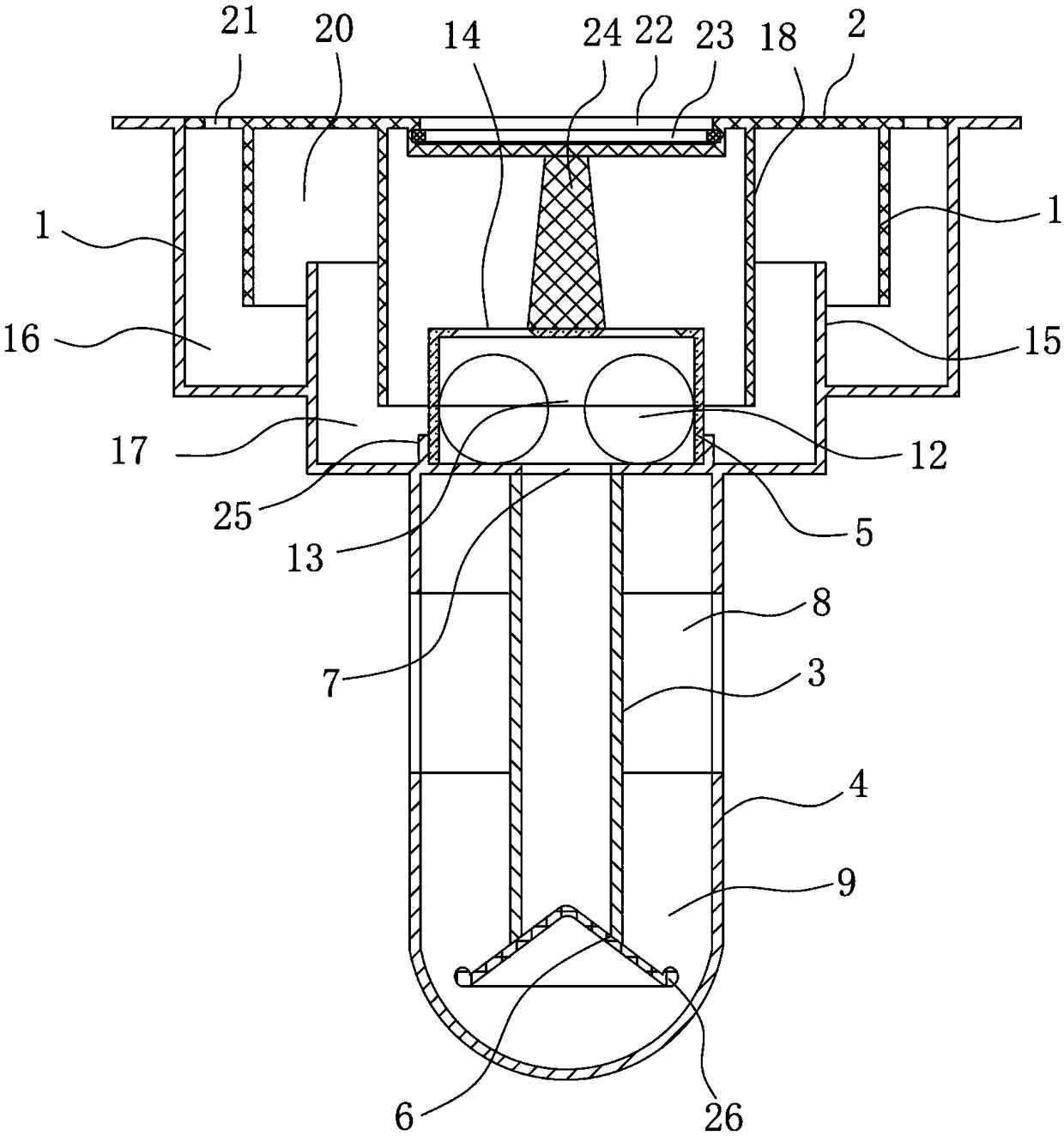
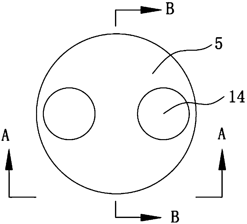
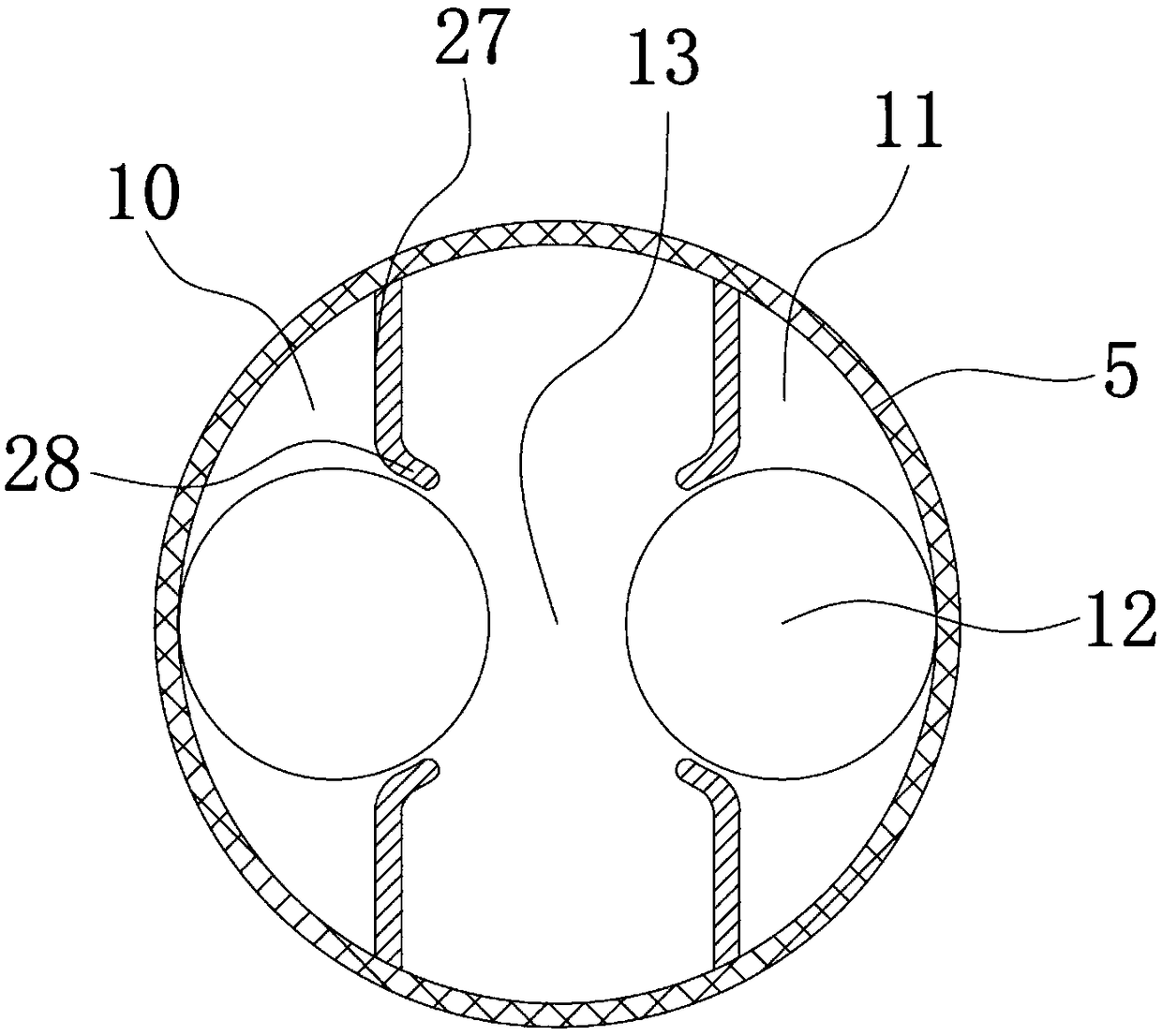
[0027] like figure 1 , figure 2 As shown, the double buoyancy ball anti-backflow floor drain includes a floor drain frame 1, a floor drain cover 2, a water guide pipe 3, an outer casing 4, a buoyancy ball cover 5 and a buoyancy sealing head 6, and the floor drain cover is arranged on the floor drain frame, and the floor drain frame is A stepped cylindrical structure with an open top and a large top and a small bottom. A lower annular baffle 15 is fixed on the shoulder of the inner step of the floor drain frame. The lower annular baffle is lower than the upper surface of the floor drain frame. The gap between the floor drain frame and the lower annular baffle The gap between them forms an outer water seal groove 16, the gap between the lower annular baffle plate and the buoyancy ball cover forms an inner water seal groove 17, and the middle part of the floor drain cover is concave to form an assembly groove 22 (see Figure 5 ), a rotating handle 23 in the shape of a semi-circular arc is installed in the assembly groove, and the rotating handle is connected to the floor drain cover through the pin shafts at both ends. Annular baffle 19, the inner annular baffle is located in the inner water seal groove, the outer annular baffle is located in the outer water seal groove, the gap between the floor drain frame, the inner annular baffle, the lower annular baffle, the annular baffle and the buoyancy ball cover A water flow channel 20 is formed, and the floor drain cover above the outer water seal tank is provided with a plurality of water filter holes 21 at intervals along the circumference, and a water outlet 7 is opened at the bottom of the floor drain frame, and the upper end of the water guide pipe is fixed on the bottom surface of the floor drain frame and communicated with the water outlet. The outer sleeve is set outside the water guide pipe and the upper end of the outer sleeve is fixedly connected with the bottom surface of the floor drain frame, the lower end of the outer sleeve is sealed, and the middle part of the outer sleeve is provided with an overflow port 8, and the gap between the outer sleeve and the water guide pipe below the overflow port forms a water seal chamber 9 , the buoyant sealing head is located in the water seal cavity between the lower end of the aqueduct and the bottom of the outer casing, the buoyant sealing head is conical, the edge of the buoyant sealing head is bent upwards to form a stable crimp 26, and the buoyant sealing head is suitable for the outlet at the lower end of the aqueduct Matching, the inner bottom of the floor drain frame protrudes upward to form an internal thread casing 25, the buoyancy ball cover is an open bottom structure, the buoyancy ball cover is located above the water outlet and is threadedly connected with the internal thread casing, and the bottom surface of the floor drain cover is fixed with a support body 24 , the support body is in the shape of a circular platform, the upper end of the support body is fixedly connected with the floor drain cover, the lower end of the support body is in contact with the buoyancy dome cover, and the left baffle group and the right baffle group are fixed inside the buoyancy dome cover, and the left baffle group and the right baffle group Both include a pair of oppositely arranged baffle plates 27 (see image 3 , Figure 4 ), the free end edge of the baffle is bent outwards to form a limit lip 28, the gap between the baffle in the left baffle group and the buoyancy ball cover forms the left buoyancy ball cavity 10, the baffle in the right baffle group The gap between the buoyancy ball and the buoyancy ball cover forms the right buoyancy ball cavity 11, the left buoyancy ball cavity and the right buoyancy ball cavity are both built with buoyancy balls 12, and the gap between the buoyancy balls forms a siphon channel 13, and the buoyancy ball above the buoyancy ball A water inlet 14 is provided at the corresponding position of the cover top surface, and the diameter of the water inlet is smaller than the diameter of the buoyancy ball, and the buoyancy ball is compatible with the water inlet.
[0028]The operating principle of the present invention is: when the water flows through the filter hole on the floor drain cover and enters the buoyancy ball cover from the water inlet hole through the water flow channel, the buoyancy ball is pressed in the left buoyancy ball cavity under the impact of the water flow and its own gravity body and the bottom of the right buoyancy ball cavity, the water flow quickly enters the aqueduct along the surface of the buoyancy ball under the siphon action of the siphon channel, and the buoyancy sealing head moves downward under the pressure of water and the impact force to open the opening at the bottom of the aqueduct , the water is discharged from the overflow port to the downpipe through the water seal chamber, and when the water flow is too large, the water in the buoyancy dome cover will be filled with water gradually, and the buoyancy ball will gradually float up under the action of buoyancy. The water outlet is closed to prevent reverse water. When the drainage is stopped, the water in the water seal chamber will form a bottom water seal, and at the same time, the buoyant sealing head will float up under the buoyancy of the water in the water seal chamber to close the opening at the bottom of the aqueduct again, thereby It plays the role of deodorization and insect prevention, and the water in the inner water seal tank and the outer water seal tank forms a horizontal double water seal.
[0029] The invention has novel and ingenious structure, fast drainage speed, good sealing effect, can effectively prevent back overflow, can be used in various places such as bathrooms, toilets, kitchens, balconies, etc., and has great popularization and application value.
[0030] The embodiment described above is only a preferred solution of the present invention, and does not limit the present invention in any form. There are other variations and modifications on the premise of not exceeding the technical solution described in the claims.

PUM

no PUM

Description & Claims & Application Information

We can also present the details of the Description, Claims and Application information to help users get a comprehensive understanding of the technical details of the patent, such as background art, summary of invention, brief description of drawings, description of embodiments, and other original content. On the other hand, users can also determine the specific scope of protection of the technology through the list of claims; as well as understand the changes in the life cycle of the technology with the presentation of the patent timeline. Login to view more.

Similar technology patents

Moisture-proof device for motor

InactiveUS20050012416A1increase in production capacitygood effect
Owner:DELTA ELECTRONICS INC

Method and system for unvarnished transmission of earphone, and earphone

ActiveCN111010646Agood effectGood transparent transmission effect
Owner:恒玄科技(北京)有限公司

Detecting system and method for partial discharge detecting sensor of GIS (gas insulated switchgear)

ActiveCN103336259AThe result is intuitive and accurategood effect
Owner:STATE GRID CORP OF CHINA +2

Pulsed plasma thruster with ceramic air spout electrode

InactiveCN101260873Agood effectSignificant increase in thrust
Owner:SHANGHAI JIAO TONG UNIV

Classification and recommendation of technical efficacy words

  • good effect
Why Eureka
Try Eureka