
A multi-channel floating ball floor drain

A floating ball type, multi-channel technology, applied in waterway systems, buildings, water supply devices, etc., can solve the problems of shaft failure, the movable door can not be completely sealed, can not be completely sealed, etc. Water pipes, the effect of not easy to accumulate water

Active Publication Date: 2020-07-03
东阳市君泰建筑工程有限公司
View PDF7 Cites 0 Cited by
  • Summary
  • Abstract
  • Description
  • Claims
  • Application Information

AI Technical Summary

Problems solved by technology

The dodge door 4 in this magnetic mechanical seal floor drain relies on the magnetic force generated between the magnet 5 and the magnet 3 to seal the water outlet of the floor drain core. Due to the poor quality of ground water, such as various reasons such as washing objects and brushing the ground, sewage There will be some iron impurities adsorbed on the magnet, which will cause a gap after the airtight movable door is closed, which cannot be completely sealed. A water outlet, once the water volume is large, it will cause water accumulation

Method used


Image

  • A multi-channel floating ball floor drain
  • A multi-channel floating ball floor drain
  • A multi-channel floating ball floor drain

Examples


Embodiment Construction

[0029] The present invention will be further described below in conjunction with the accompanying drawings and specific embodiments.

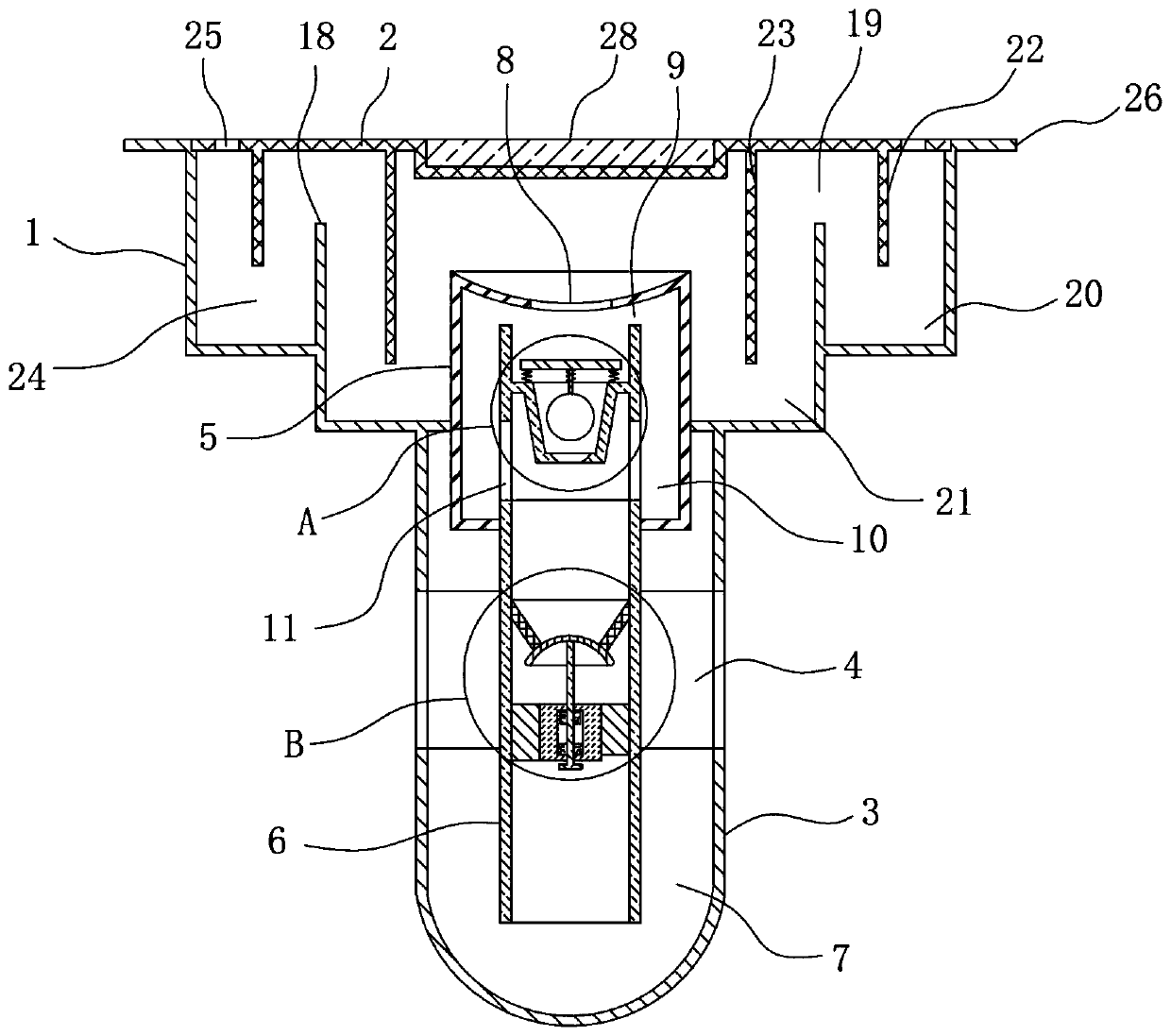
[0030] Such as figure 1 A multi-channel floating ball floor drain is shown, including a floor drain frame 1, a floor drain cover 2 compatible with the floor drain frame, and a floor drain core. The top edge of the frame is bent outwards to form a clamping flange 26, and the shoulder of the step surface in the floor drain frame is fixed with a water retaining ring 18 that is homogeneous with the floor drain frame. The space between the water retaining ring and the water retaining ring forms the first water storage tank 20, and the space between the water retaining ring and the water retaining pipe forms the second water retaining tank 21. The bottom surface of the floor drain cover is fixed with an inner water retaining ring 23 and an outer water retaining ring 22. The water retaining ring, the outer water retaining ring and the floor drain cov...


PUM


Abstract

The invention discloses a multi-flow channel floating ball type floor drain. The floor drain comprises a floor drain frame, a floor drain cover and a floor drain core. A drainage pipe is arranged on the bottom face of the floor drain frame, a drainage port is formed in the middle of the drainage pipe, the floor drain core comprises a water blocking pipe with both ends sealed, a water guiding pipeand a floating ball type drainage mechanism, and the floating ball type drainage mechanism includes a floating ball, a baffle and a water collection groove; the water blocking pipe upward penetrates through the bottom face of the floor drain frame, the water guiding pipe upward penetrates through the water blocking pipe, a gap between the drainage pipe below the drainage port and the water guidingpipe forms a water seal cavity, a water inlet is formed in the upper end face of the water blocking pipe, a gap between the upper end of the water guiding pipe and the water blocking pipe forms an overflow port, and a gap between the water guiding pipe and the water blocking pipe forms an overflow groove; side overflow ports are formed in diversion pipes on one side of the overflow groove, a connecting ring is arranged on the inner wall of the water guiding pipe, the baffle is fixedly connected with the connecting ring through springs, and the floating ball is located in the water collectiongroove, matched with a water outlet in the bottom of the water collection groove and connected with the baffle through a connecting rod. The floor drain has multiple sealing structures and a good sealing effect and is rapid in drainage, unlikely to block and high in self-cleaning capability.

Description

technical field [0001] The invention relates to a floor drain, in particular to a multi-channel float type floor drain. Background technique [0002] The floor drain is an important interface connecting the drainage pipe system and the indoor floor. As an important part of the drainage system in the residence, its performance directly affects the quality of the indoor air, and is very important for the odor control in the bathroom. [0003] The structure of the traditional water-sealed floor drain is a bell type, like a buckle bowl structure buckled on the mouth of the water pipe, forming a "U-shaped trap", using the "water seal" in the trap to achieve the sealing effect. But the water of this floor drain If the seal is shallow and the amount of water is too small, it will dry up due to factors such as time and dry weather and will return to smell. The most important thing is that this kind of floor drain usually only has one outlet. Once the water volume is large, the water...

Claims


Application Information

Patent Timeline
Patent Type & Authority Patents(China)
IPC IPC(8): E03F5/04E03F5/042E03F7/06
CPCE03F5/0407E03F5/042E03F7/06E03F2005/0417E03F2005/0418
Inventor 不公告发明人
Owner 东阳市君泰建筑工程有限公司
Features
  • Generate Ideas
  • Intellectual Property
  • Life Sciences
  • Materials
  • Tech Scout
  • Unparalleled Data Quality
  • Higher Quality Content
  • 60% Fewer Hallucinations
Learn More