Positioning means

A technology of positioning device and positioning part, which is applied in the direction of connecting components, pins, mechanical equipment, etc., can solve the problems of inconvenient use, affecting the time and smoothness of disassembly and assembly operations, and increasing the cost of processing operations, so as to achieve the effect of improving convenience

Active Publication Date: 2020-06-23
HANWIT PRECISION IND LTD
View PDF6 Cites 0 Cited by
  • Summary
  • Abstract
  • Description
  • Claims
  • Application Information

AI Technical Summary

Problems solved by technology

[0004] However, since the two first ring edges A22 and the two second ring edges A23 of the limit ring A2 of the sleeve A are arranged in a staggered manner, and the two long protruding rods on the inner wall of the sliding hole C2 of the outer sleeve C C21 and the two short protruding rods C22 are oppositely arranged, so when the outer sleeve C is pressed and rotated, the two long protruding rods C21 of the outer sleeve C can only move toward the two second rings with smaller outer diameters at the same time. Rotate in the direction of side A23, so that whether the outer sleeve C is in the locked or unlocked state, it can only be used by reciprocating rotation in a single direction (clockwise or counterclockwise), so that when the rotary rod B2 of the turnbuckle component B After being locked on the preset fixed plate, subsequent users cannot know whether the turnbuckle component B is in the locked or unlocked state by turning it (because both locking and unlocking are rotated 90 degrees), resulting in It affects the time and fluency of the overall disassembly and assembly operation, and is not only time-consuming and inconvenient, but also the indicator part C4 must be further processed on the top surface of the outer sleeve C to understand the locking and unlocking of the positioning device Direction, thereby increasing the cost of processing operations
[0005] In addition, most of the general positioning devices are installed in the cabinets of telecom bureaus, industrial computers, work machines, servers and other equipment. Due to the dim light inside the cabinets, the indicating part C4 of the outer sleeve C of the positioning device is not easy to see and identify. So that the user can only feel whether it is locked or unlocked in operation, and because the operation experience is the same when locked or unlocked, it causes a lot of inconvenience in use

Method used


Image

  • Positioning means
  • Positioning means
  • Positioning means

Examples


Embodiment Construction

[0035] In order to achieve the above-mentioned purpose and effect, the technical means adopted in the present invention, its structure, and the method of implementation, etc., are hereby described in detail with respect to the preferred embodiments of the present invention. Its features and functions are as follows, so that it can be fully understood.

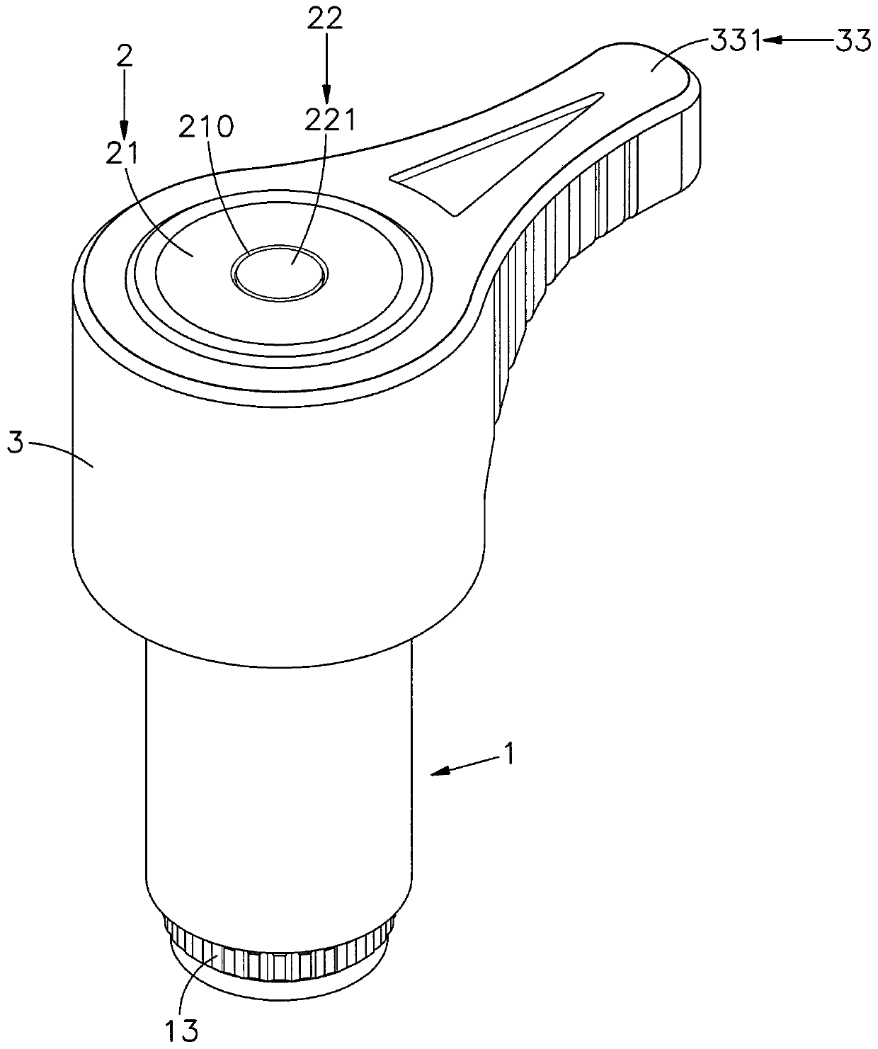
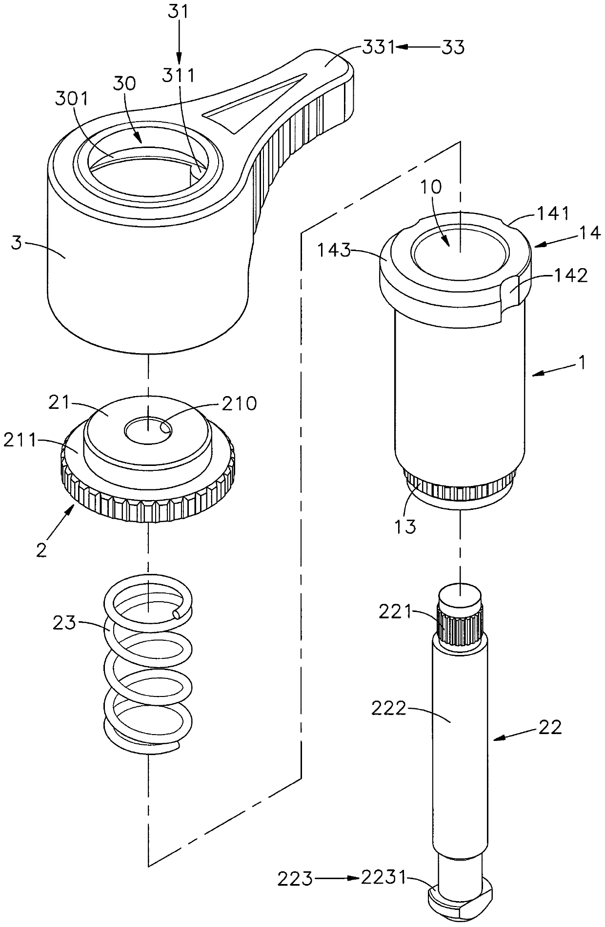
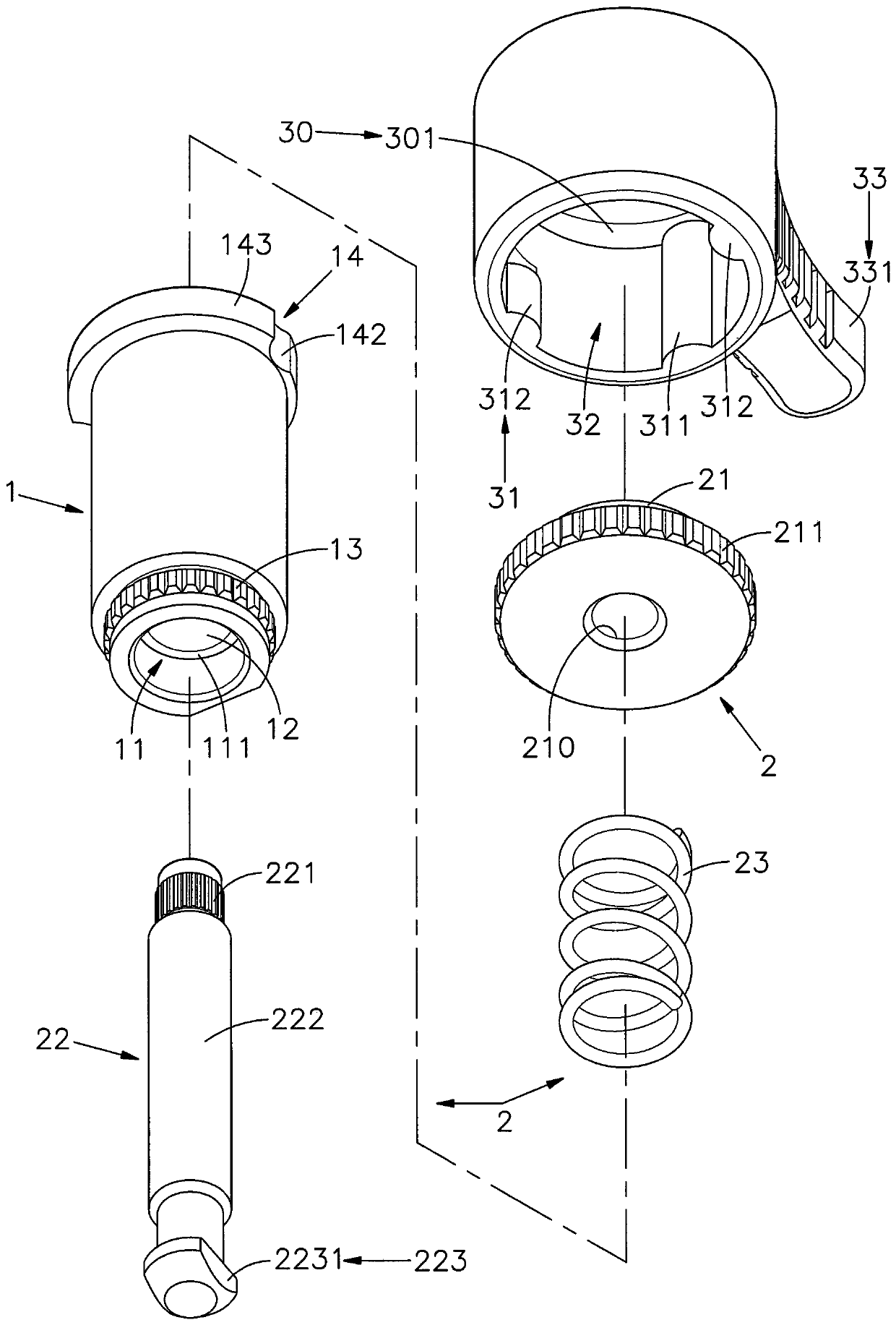
[0036] see figure 1 , figure 2 , image 3 , Figure 4 As shown, it is a three-dimensional appearance diagram, a three-dimensional exploded view, a three-dimensional exploded view of another angle of view, and a side sectional view of the present invention. It can be clearly seen from the figures that the positioning device of the present invention includes a sleeve 1, a turnbuckle Component 2 and drive sleeve 3, wherein:

[0037] The sleeve 1 has a hollow perforation 10 inside, and a swivel space 11 with a larger aperture is provided on one side of the perforation 10, and a shaft hole 12 with a reduced aperture is provided...


PUM


Abstract

The invention provides a positioning device. A rotation space is arranged on one side of a penetrating hole in a sleeve. A limiting ring body is arranged at the top of the outer side of the sleeve. Afirst limiting slot, two second limiting slots and a convex ring between the two second limiting slots are arranged on the outer edge of the limiting ring body. A positioning element penetrating intothe penetrating hole and an elastic element arranged on the positioning element in a sleeving mode are arranged on the bottom surface of a rod head of a rotary buckling element outside the sleeve. Therod head is positioned in an assembling space of a driving sleeve body. A long convex rod and two short convex rods corresponding to the first limiting slot and the two second limiting slots respectively are arranged in a sliding inner hole formed in the one side of the assembling space and covering the limiting ring body. During locking operation, the driving sleeve body can rotate in two directions. But during unlocking operation, the driving sleeve body can only rotate in one direction. Therefore, the purpose of easily recognizing the locking or unlocking state through different operationhand feelings is realized.

Description

technical field [0001] The invention relates to a positioning device, especially after the drive sleeve outside the sleeve is pressed down, the turnbuckle element in the sleeve can be locked by two-way rotation. However, the turnbuckle element can only be unlocked. Through the reverse one-way rotation, the locked or unlocked state can be known by the feel of the rotation, so as to achieve the purpose of simple and fast operation intuition. Background technique [0002] Press, when the general panel (board-to-board) is combined, it is locked by using the positioning screw with the knob, the collar and the screw, and the screw and the collar can be fixed on the first panel and rotated on the first panel. The knob makes the screw lock into the second panel to form a preset position, and then use the hand tool to lock the screw, so that the first panel and the second panel are locked and fixed as one, and can be used in telecom bureau cabinets, industrial computers , working ma...

Claims


Application Information

Patent Timeline
Patent Type & Authority Patents(China)
IPC IPC(8): F16B13/04
CPCF16B13/04
Inventor 吴明德张景凯
Owner HANWIT PRECISION IND LTD
Why Eureka
Try Eureka