Domestic water tap

A faucet and household technology, which is applied in the field of kitchen and bathroom, can solve the problems of only drinking water directly, affecting the appearance and user use, and cannot be used for washing, so as to achieve the effect of preventing pollution

Active Publication Date: 2018-11-13
泉州东泰卫浴有限公司
View PDF6 Cites 0 Cited by
  • Summary
  • Abstract
  • Description
  • Claims
  • Application Information

AI Technical Summary

Problems solved by technology

[0002] At present, some of the faucets sold on the market can only release cold water or hot water, and some use a thermostat valve to mix cold water and hot water before releasing appropriate warm water. The domestic tap water purifiers that appear on the market today are generally set as independent devices, which can only be used for drinking water directly and cannot be used for washing, and some faucets with water purification function install the water purification device at the outlet of the faucet, which affects the appearance and appearance. user use

Method used


Image

  • Domestic water tap
  • Domestic water tap
  • Domestic water tap

Examples


Embodiment 1

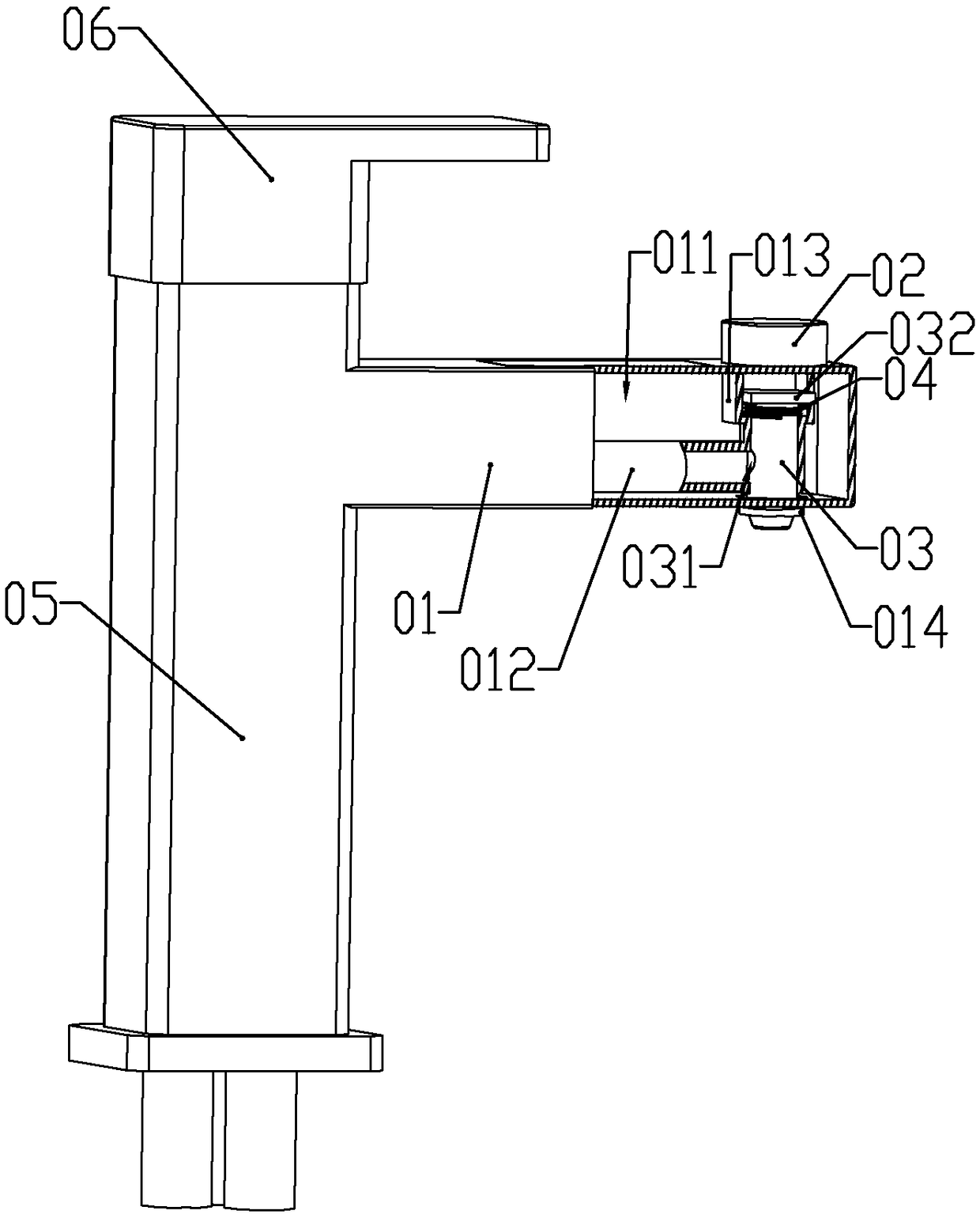
[0045] according to Figure 1 to Figure 8 As shown, a household faucet described in this embodiment includes a standpipe 05 for fixed installation, a horizontal pipe 01 horizontally arranged on the upper part of the standpipe; a rotary rheostat is installed at the upper end of the standpipe; the A handle 06 is fixedly connected to the rotating shaft of the rotary rheostat.

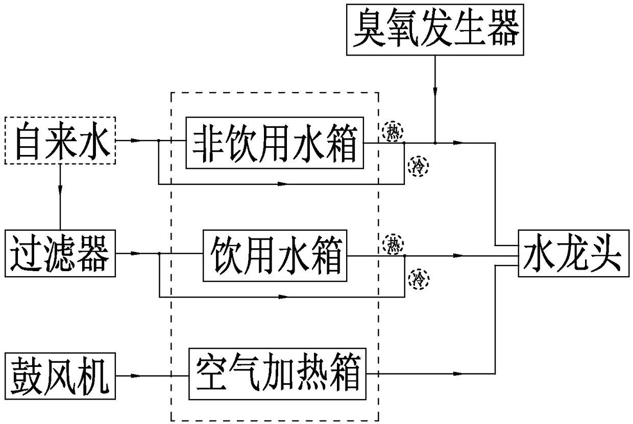
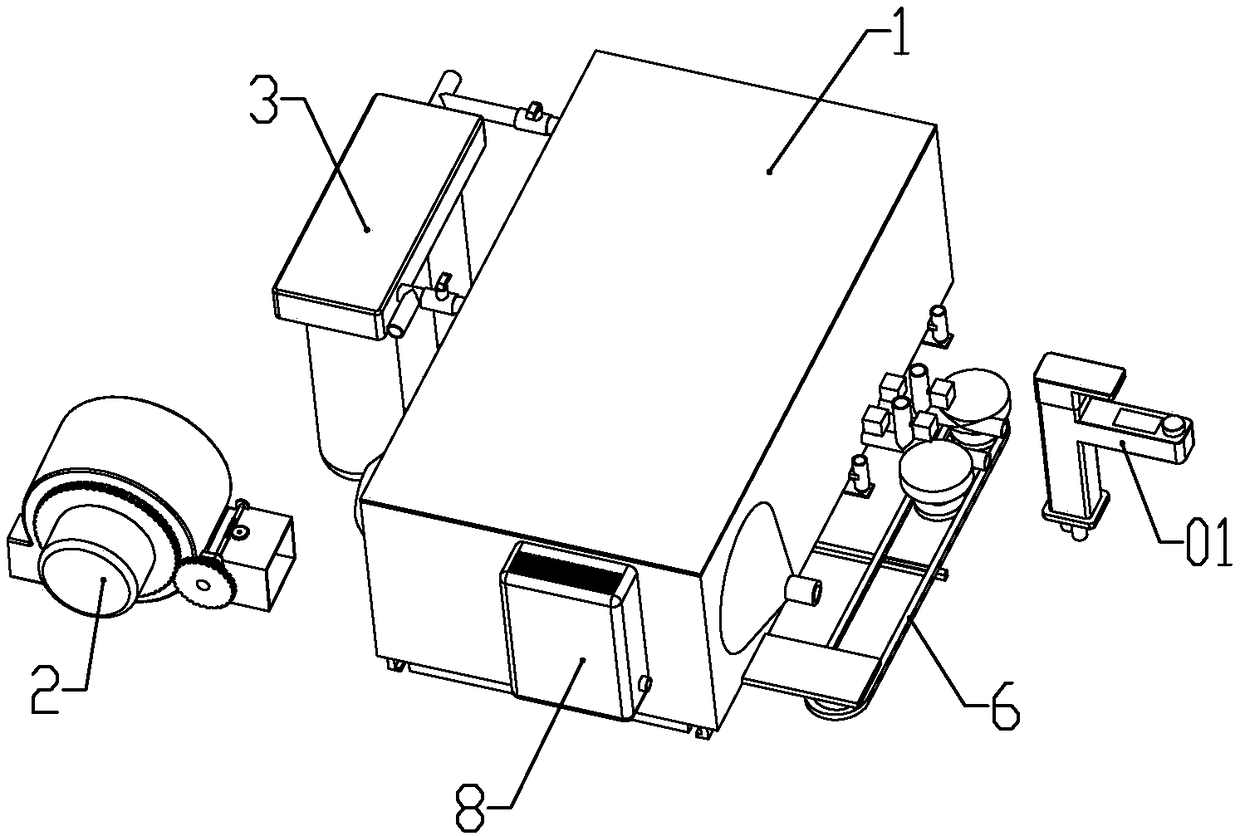
[0046] The faucet is connected to a heating box 1 through a pipeline; the end of the heating box away from the connection to the faucet is respectively connected to a filter 3 for filtering tap water and a blower 2 for generating air flow; the bottom of the heating box is slidably connected to an induction cooker 5 .

[0047] Described heating box comprises the non-drinkable water tank 11 that is communicated with running water, the potable water tank 12 that is communicated with the water outlet of filter and the air heating tank 13 that is communicated with blower; Described non-drinkable water tank, de...

Embodiment 2

[0063] combine Figure 9-11 As shown, the present embodiment has made the following improvements on the basis of Embodiment 1: the blower includes a cylindrical housing 21; a driving motor 22 is installed outside the housing; the output shaft of the driving motor is connected to the housing The body is concentric; the output shaft of the drive motor is located in the housing and two fans 23 are installed; the two fans are centrifugal fans; the middle of the two fans facing the side of the drive motor is formed with a ratchet 231; The directions of the two ratchets are opposite; the output shaft of the drive motor is fixedly connected with a ratchet chuck 27 that cooperates with the ratchet; the housing is fixedly connected with a partition plate 213 parallel to the fan; The partition plate is located between the two fans; the outer peripheral bottom of the housing is formed with horizontally arranged rectangular first air outlets 211 and second air outlets 212; the width of th...


PUM


Abstract

The invention belongs to the technical field of kitchen and bath and discloses a domestic water tap. The domestic water tap comprises a vertical pipe, a horizontal pipe and a handle, wherein the vertical pipe is fixedly installed; the horizontal pipe is horizontally arranged at the upper part of the vertical pipe; the water tap is connected with a heating box through a pipeline; one end, far awayfrom the water tap, of the heating box is correspondingly connected with a filter and an air blower, wherein the filter is used of filtering tap water, and the air blower is used for generating air flow; and the bottom of the heating box is slidably connected with an electromagnetic oven. By using the domestic water tap provided by the invention, drinking water and non-drinking water are discharged from the water tap via special pipelines for the drinking water and the non-drinking water separately so as to prevent the non-drinking water from polluting the drinking water; a valve pipe for thedrinking water is controlled to stretch and retract by virtue of an electromagnet; and when a user does not need the drinking water, the valve pipe retracts into the water tap so as to prevent the external environment from polluting the valve pipe.

Description

technical field [0001] The invention belongs to the technical field of kitchen and bathroom, and in particular relates to a household faucet. Background technique [0002] At present, some of the faucets sold on the market can only release cold water or hot water, and some use a thermostat valve to mix cold water and hot water before releasing appropriate warm water. The domestic tap water purifiers that appear on the market today are generally set as independent devices, which can only be used for drinking water directly and cannot be used for washing, and some faucets with water purification function install the water purification device at the outlet of the faucet, which affects the appearance and appearance. user use. Contents of the invention [0003] The technical problem to be solved by the present invention is to provide a household faucet aiming at the deficiencies of the prior art. [0004] In order to achieve the purpose of the present invention, the following...

Claims


Application Information

Patent Timeline
Patent Type & Authority Applications(China)
IPC IPC(8): F16K11/22F16K49/00F04D25/08F04D25/16F04D29/42
CPCF04D25/08F04D25/166F04D29/4246F16K11/22F16K49/002
Inventor 郑健
Owner 泉州东泰卫浴有限公司
Why Eureka
Try Eureka