Optical imaging system

An optical imaging system, camera technology, applied in optics, optical components, instruments, etc., can solve problems such as the inability to effectively expand the camera angle of view

Inactive Publication Date: 2018-11-13
GUILIN UNIV OF ELECTRONIC TECH
View PDF8 Cites 1 Cited by
  • Summary
  • Abstract
  • Description
  • Claims
  • Application Information

AI Technical Summary

Problems solved by technology

[0004] Based on the technical problems existing in the background technology, the present invention proposes an optical imaging system, which has the characteristics of realizing wide-range or even full-angle viewing through rotation, and at the same time expanding the viewing angle. The optical imaging lens has a large field of view, but it cannot effectively expand the camera's viewing angle

Method used


Image

  • Optical imaging system
  • Optical imaging system

Examples


Embodiment Construction

[0016] The following will clearly and completely describe the technical solutions in the embodiments of the present invention with reference to the accompanying drawings in the embodiments of the present invention. Obviously, the described embodiments are only some, not all, embodiments of the present invention. Based on the embodiments of the present invention, all other embodiments obtained by persons of ordinary skill in the art without making creative efforts belong to the protection scope of the present invention.

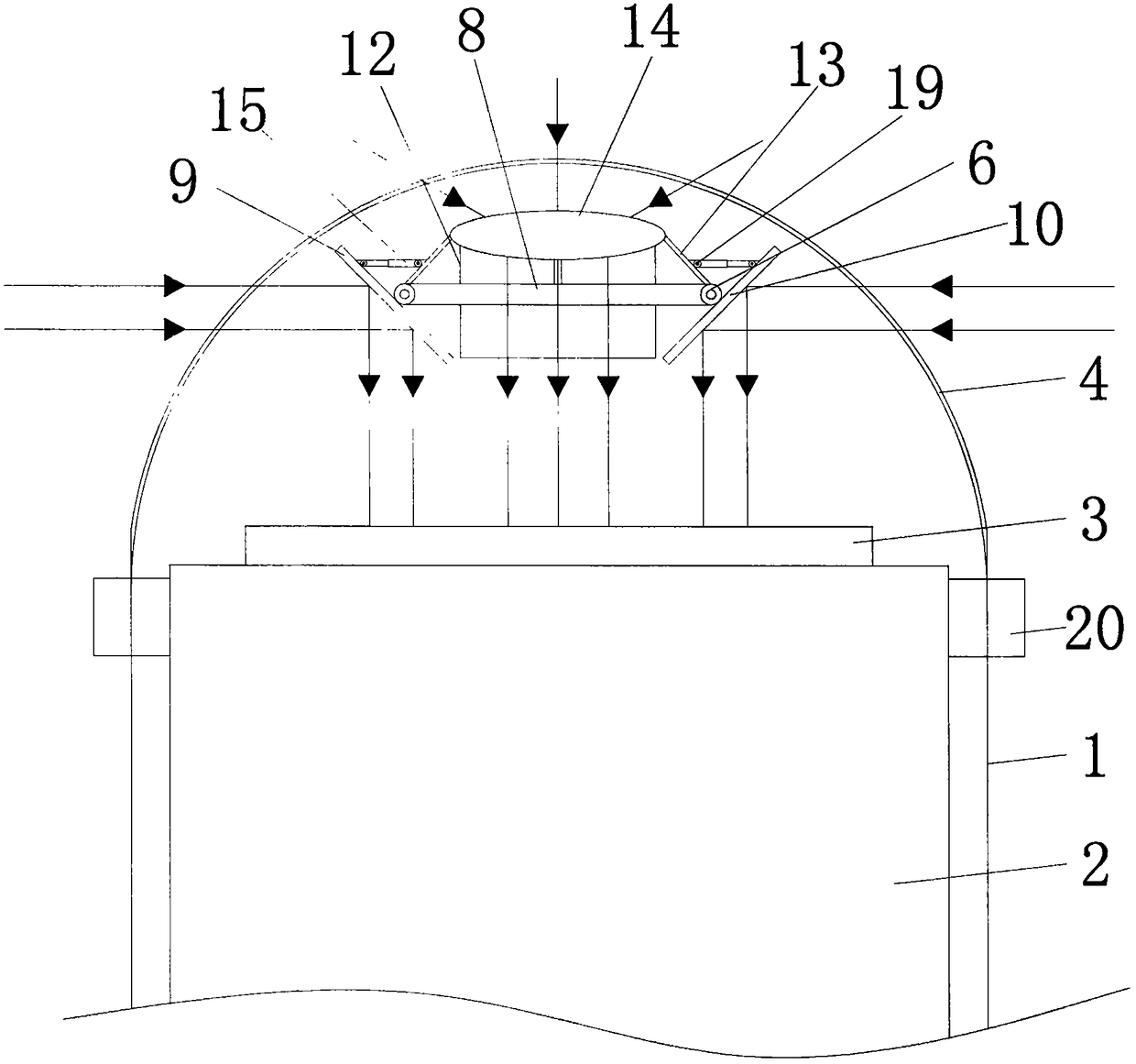
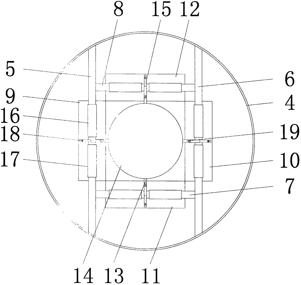
[0017] see Figure 1-2 , the present invention provides a technical solution: an optical imaging system, including a housing 1, a camera 2 is fixedly installed inside the housing 1, a lens 3 is arranged on the top of the camera 2, and a Glass protection cover 4, the surface of glass protection cover 4 inner walls is fixedly connected with first fixed rod 5, the surface of glass protection cover 4 inner walls and is positioned at the right side of first fixed r...


PUM


Abstract

The invention discloses an optical imaging system. The optical imaging system comprises a casing, wherein a camera is fixedly mounted in the casing; a lens is arranged at the top of the camera; a glass protecting cover is arranged in the position, corresponding to the lens, of the top of the casing; a first fixed rod is fixedly connected with the surface of the inner wall of the glass protecting cover; a second fixed rod is fixedly connected with the surface of the inner wall of the glass protecting cover and located on the right side of the first fixed rod; a first connecting rod and a secondconnecting rod are fixedly connected between the first fixed rod and the second fixed rod; a first reflecting mirror is rotationally connected with the surface of the first fixed rod; a second reflecting mirror is rotationally connected with the surface of the second fixed rod. According to the optical imaging system, under the cooperation of the first reflecting mirror, the second reflecting mirror, a third reflecting mirror, a fourth reflecting mirror, a convex lens and electric drive pushers, the problem that a large view field range of an optical imaging lens is realized by rotating the angle of a prism reflecting surface, but the viewing angle of an existing camera cannot be effectively expanded is solved.

Description

technical field [0001] The invention relates to the technical field of optical imaging, in particular to an optical imaging system. Background technique [0002] As imaging lenses are more and more widely used in monitoring, security, vehicle, projection, special environment detection, monitoring and biomedical detection, the application of large field of view and large angle range optical imaging lenses will also be a development trend . However, as far as the current technology and engineering process are concerned, it is still difficult to achieve ultra-large field of view and large-angle imaging. On the one hand, in terms of design, large-angle imaging will produce large distortion, because when the viewing angle is greater than 120°, the distortion will appear The rapid growth makes the imaged image seriously distorted, the aberration is difficult to correct, and the large-angle imaging system is easy to make mistakes in the software design of light; on the other hand,...

Claims


Application Information

Patent Timeline
Patent Type & Authority Applications(China)
IPC IPC(8): G02B17/00G02B13/06
CPCG02B13/06G02B17/00
Inventor 白雁力姚荣彬高海英
Owner GUILIN UNIV OF ELECTRONIC TECH
Why Eureka
Try Eureka