Large coal ash storage tank and coal ash storage system

A storage system and storage tank technology, applied in the field of fly ash storage system, can solve the problems of many dead spots in the coal ash storage tank, high energy consumption, and low fluidization pressure of Roots blower, so as to reduce the maintenance workload, Increase the effective volume of storage and eliminate the effect of stacking dead ends

Active Publication Date: 2013-04-24
CHINA POWER ENG CONSULTING GRP CORP EAST CHINA ELECTRIC POWER DESIGN INST
View PDF7 Cites 6 Cited by
  • Summary
  • Abstract
  • Description
  • Claims
  • Application Information

AI Technical Summary

Problems solved by technology

[0006] The first type of coal ash storage system is the pulverized coal storage tank commonly used in domestic power plants. The disadvantages are: long-term storage of fly ash will easily form compaction in the coal ash storage tank, reducing the effective storage tank capacity and easily forming Potential safety hazard; the fluidization pressure of the Roots fan is low. When the material level is high, the pressure rises, which is easy to form a "jump", the overall fluidization, and high energy consumption
[0007] The second type of coal ash storage system is widely used in Europe. The disadvantages are: high equipment reliability requirements. Since the gasification chute is partly built in the coal ash storage tank, the accuracy and reliability requirements of the central unloading equipment are higher than other systems. The coal ash storage tank has high requirements and high cost; the built-in decompression cone occupies 1 / 4~1 / 5 of the effective volume of the ash storage, wasting a large storage space
[0008] The third type of coal ash storage system is used in a small number of large-scale cement silos and fly ash storage tanks in China. The disadvantages are: the upward discharge is adopted, and there are many dead ends in the coal ash storage tank. The lower part of the coal ash storage tank is about There are 3~4 meters of ash deposits that cannot be removed; the energy consumption of the system is high, and the side wall discharge is used to generate a large positive pressure in the coal ash storage tank. The structural strength of the coal ash storage tank is high, and the energy consumption is large

Method used


Image

  • Large coal ash storage tank and coal ash storage system
  • Large coal ash storage tank and coal ash storage system
  • Large coal ash storage tank and coal ash storage system

Examples


Embodiment Construction

[0037] Preferred embodiments of the present invention will be described in detail below with reference to the accompanying drawings, so as to better understand the purpose, features and advantages of the present invention. It should be understood that the embodiments shown in the drawings are not intended to limit the scope of the present invention, but only to illustrate the essence of the technical solutions of the present invention.

[0038] The main technical terms of the present invention are explained below.

[0039] Large fly ash storage tank: generally refers to the storage effective volume of 3000m 3 ~50000m 3 Silos or tanks

[0040] Positive pressure fluidization: 0.1~1.0Mpa compressed air is used as the carrier to fluidize the solid particle material.

[0041] Underdrawing discharge: the material is discharged from the bottom of the storage tank.

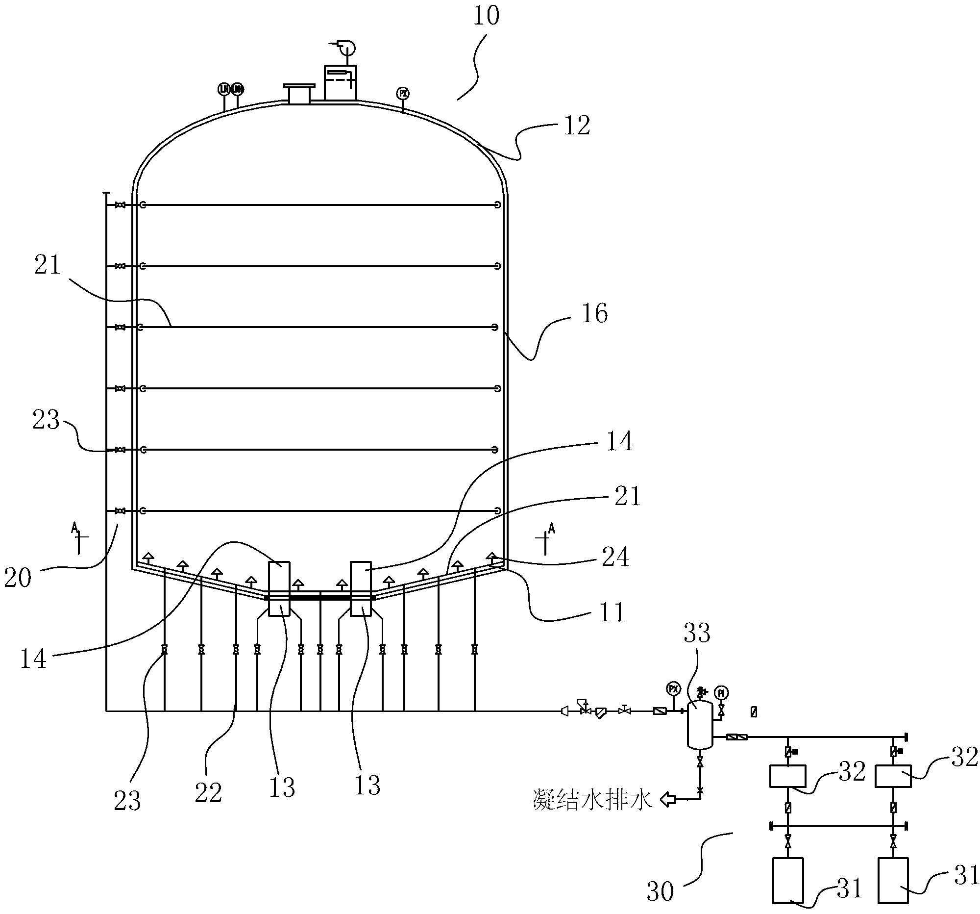
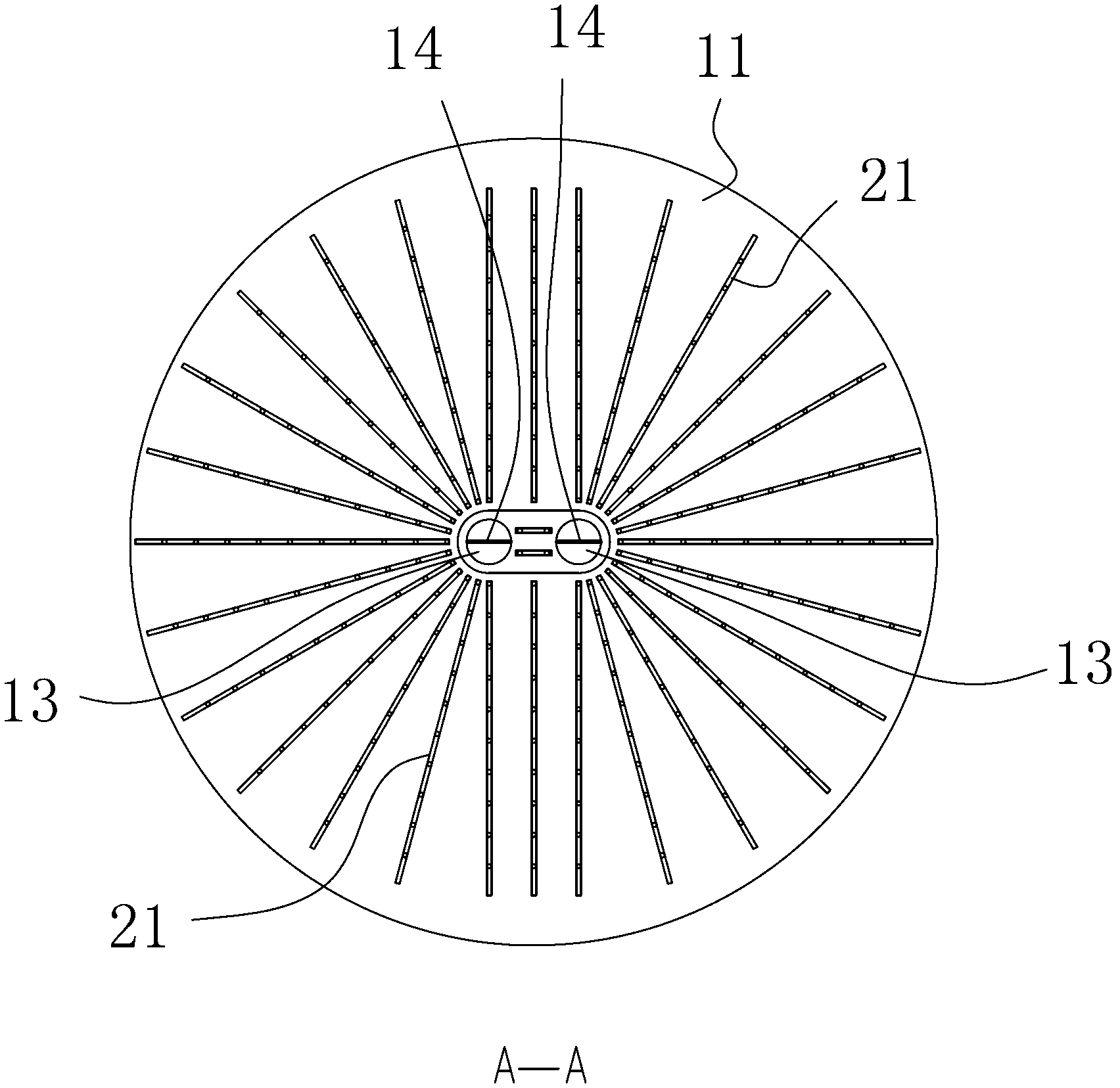
[0042] figure 1 A schematic structural view of the fly ash storage system of the present invention is shown. Such...


PUM


Abstract

The invention relates to a large coal ash storage tank and a coal ash storage system. The coal ash storage system comprises a large coal ash storage tank, a divided fluidization pipeline system and a compressed air source system. The large coal ash storage tank is provided with a hollow tubular structure and comprises a storage tank base part, a storage tank lateral wall and a storage tank top part, wherein a plurality of material discharging ports are arranged on the storage tank base part, and decompression conical partition boards are arranged on the material discharging ports. The divided fluidization pipeline system comprises a multilayer fluidization pipeline arranged on the storage tank lateral wall along the height direction of the storage tank, and a plurality of fluidization nozzles are arranged on the fluidization pipeline. The compression air source system blows air with certain pressure into the storage tank through the divided fluidization pipeline system, so that the coal ash in the storage tank can be fluidized in positive pressure mode. The large coal ash storage tank and the coal ash storage system are simple in structure, less in maintenance working load and high in reliability, fully fluidize the coal ash, greatly reduce and avoid storage accumulation dead angles, prolong the coal ash storage time and enlarge the effective using volume of a storage cabin.

Description

technical field [0001] The invention relates to thermal power generation, in particular to a fly ash storage system of a thermal power plant. Background technique [0002] At present, the capacity of a single fly ash storage tank in a power plant is generally 3500m 3 Below, the storage days shall not exceed 2 days. The adopted coal ash storage tank fluidization and discharge technology can only be applied to the short-term storage of fly ash. If the storage days become longer, the fly ash will easily harden on the bottom of the storage tank, the wall of the storage tank and the area of ​​the discharge port. The work of the storage tank brings great potential safety hazards, for example, when personnel overhaul, the fly ash on the storage tank wall collapses and personnel are buried. [0003] At the same time, the fly ash is piled up in the ash yard, generating serious dust flying and causing great air pollution. Heavy metal substances in fly ash can easily penetrate into...

Claims


Application Information

Patent Timeline
Patent Type & Authority Applications(China)
IPC IPC(8): B65D88/72B65D90/02
Inventor 冯斌梅飞虎沈兵林磊应祎平冯丽敏金剑勇
Owner CHINA POWER ENG CONSULTING GRP CORP EAST CHINA ELECTRIC POWER DESIGN INST
Why Eureka
Try Eureka