Gas distributor and reactor

A gas distributor and reactor technology, applied in chemical instruments and methods, chemical/physical processes, etc., can solve problems such as general performance, impossibility of improvement, waste of reactor volume, etc.

Active Publication Date: 2019-09-06
CHNA ENERGY INVESTMENT CORP LTD +1
View PDF8 Cites 1 Cited by
  • Summary
  • Abstract
  • Description
  • Claims
  • Application Information

AI Technical Summary

Problems solved by technology

The head-type gas distributor usually sets a closed gas chamber at the bottom of the reactor for gas redistribution, but this causes a waste of reactor volume, and there is a risk of the slurry in the reactor being poured into the head; the filling type The structure of the distributor is simple, but once the solid particles enter the packing layer during operation, it is difficult to be blown out, and it is eas

Method used


Image

  • Gas distributor and reactor
  • Gas distributor and reactor
  • Gas distributor and reactor

Examples


Embodiment approach

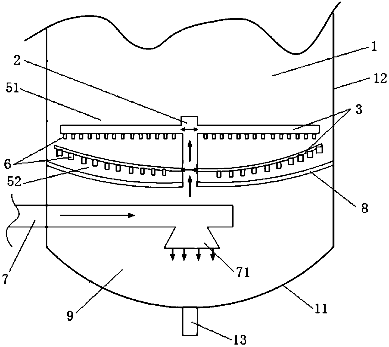
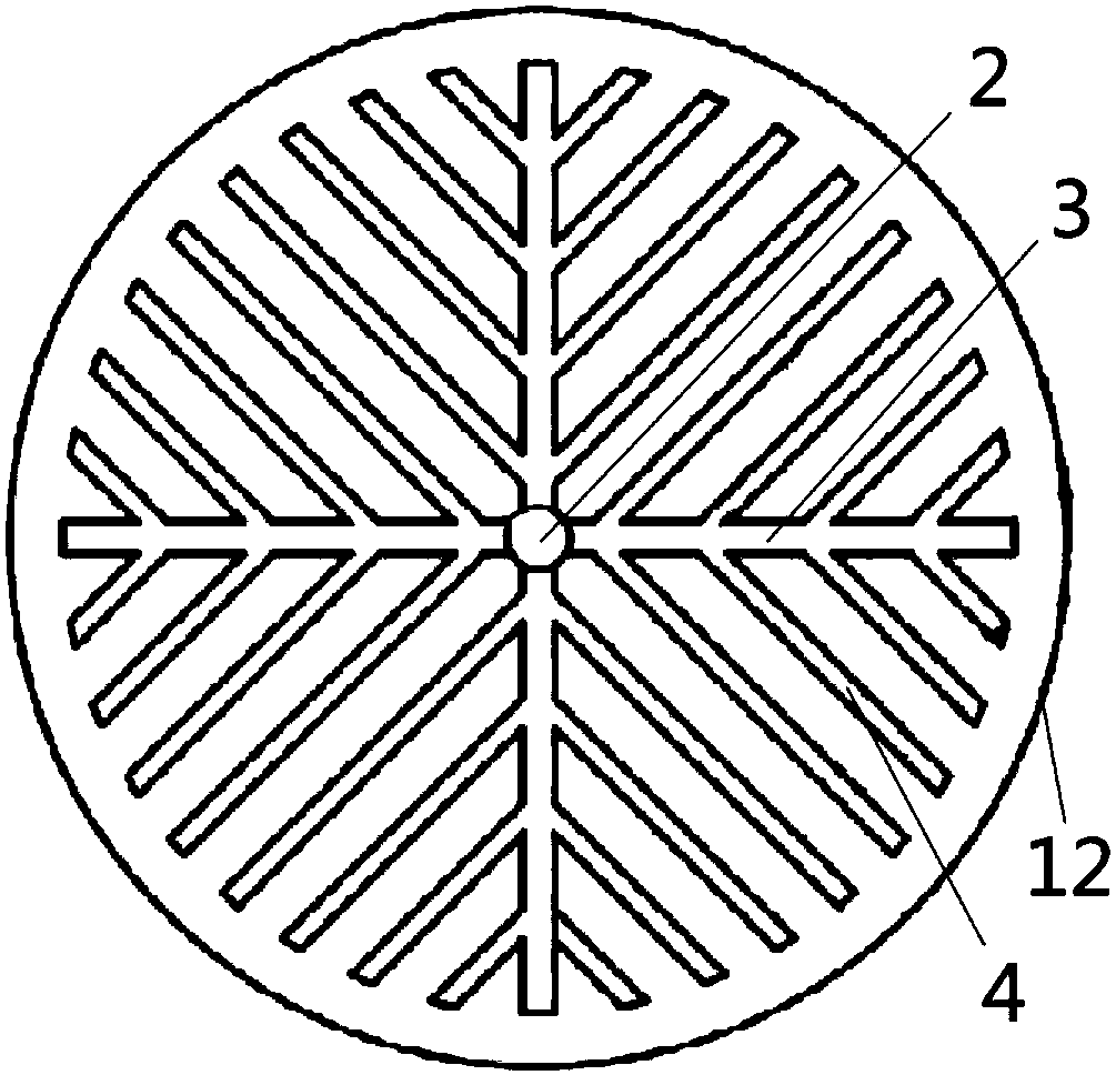
[0054] continue to refer figure 1 and figure 2 , according to an embodiment of the present invention, the gas distributor includes a gas riser 2, and the gas riser 2 is connected to the center of each layer of pipeline components. Such as figure 2 As shown in , each feed distribution pipe 3 is evenly distributed radially along the circumference of the gas riser 2 . In reactions comprising this gas distributor, said gas riser 2 extends along the longitudinal centerline of the reactor 1 . In this way, it can be ensured that the pressure and velocity of the gas entering each feed distribution pipe 3 are substantially equal, so that the distribution of the gas is uniform. A plurality of nozzles 6 are distributed on each feed distribution pipe 3, and these nozzles 6 can be arranged at equal intervals, or can be arranged in other ways, but preferably, the flow velocity of the gas ejected from each nozzle 6 should be as close as possible. quite.

[0055] Further, according to ...


PUM


Abstract

The present invention discloses a gas distributor and a reactor. The gas distributor includes a main gas inlet tube, a dummy plate, at least one gas riser tube and a plurality of layers of top-and-bottom spaced pipeline assemblies from the bottom to the top, one end of the gas riser tube go through the dummy plate, and the other end goes through each layer of the pipeline assembly; and each layerof the pipeline assembly includes a plurality of feed distribution tubes that are connected to the gas riser tube at one ends and closed at the other ends, and a plurality of nozzles communicated withthe feed distribution tubes, and a gas introduced through the main gas inlet tube goes through the gas riser tube, is distributed in the feed distribution tubes, and is sprayed out through the nozzles, wherein the internal diameters of the feed distribution tubes in every layer of the pipeline assembly gradually decrease along a direction away from the dummy plate to the vicinity of the dummy plate, and the internal diameters of the nozzles in every layer of the pipeline assembly gradually increase along the direction away from the dummy plate to the vicinity of the dummy plate. The gas distributor can make gas streams respectively be uniform when used in the reactor in order to prevent catalyst deposition and wearing and avoid a slurry from blocking the main gas inlet tube.

Description

technical field [0001] The invention relates to the field of chemical industry, in particular to a gas distributor and a reactor. Background technique [0002] With the continuous rise of oil prices in recent years, people pay more and more attention to the development of technologies to produce alternative oil products. Syngas is produced through coal, natural gas or other substances, and then according to the requirements of the Fischer-Tropsch synthesis catalyst for synthesis gas, through water-gas shift and synthesis The gas purification process processes the syngas, and uses the treated syngas as a raw material to produce hydrocarbons through Fischer-Tropsch synthesis, and at the same time produces oxygenated compounds, which are then processed by mature petroleum processing technology to produce high-quality, environmentally friendly oil. Taste. The development of Fischer-Tropsch synthesis technology is of great significance to the development of production technology...

Claims


Application Information

Patent Timeline
IPC IPC(8): B01J8/08
CPCB01J8/085
Inventor 杜冰卜亿峰张奉波张晓芳孙永伟
Owner CHNA ENERGY INVESTMENT CORP LTD
Why Eureka
Try Eureka