Card connector

A card connector and side connection technology, which is applied in the direction of telephone connectors, connections, parts of connection devices, etc., can solve the problems of the design freedom limit of the composite card card connector, contact bending, etc., and achieve cheap and appropriate Manufacturing, prevention of false contact, and high degree of design freedom

Inactive Publication Date: 2018-11-13
SMK CO LTD
View PDF2 Cites 1 Cited by
  • Summary
  • Abstract
  • Description
  • Claims
  • Application Information

AI Technical Summary

Problems solved by technology

[0013] However, in the prior art as described above, it is necessary to secure a space for arranging a plurality of contact groups on the inner bottom surface of the tray insertion portion, and accordingly, there is a problem that the design freedom of the multi-card and the card connector is limited.
[0014] And, in this kind of card connector, because it is the structure that one contact group corresponding to each pad group is disposed close to the inner side of the tray insertion and removal direction of the bottom plate of the tray insertion part, if the card is inserted and removed If the tray is inserted obliquely, the card tray may come into contact with the contacts of the near-side contact group from an unexpected direction, and the contacts may be bent.

Method used


Image

  • Card connector
  • Card connector
  • Card connector

Examples


Embodiment Construction

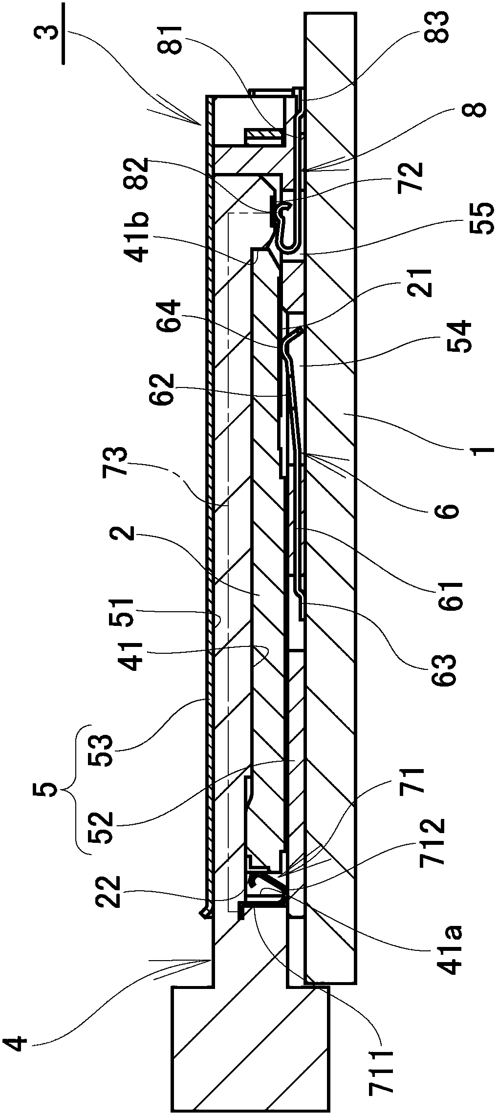
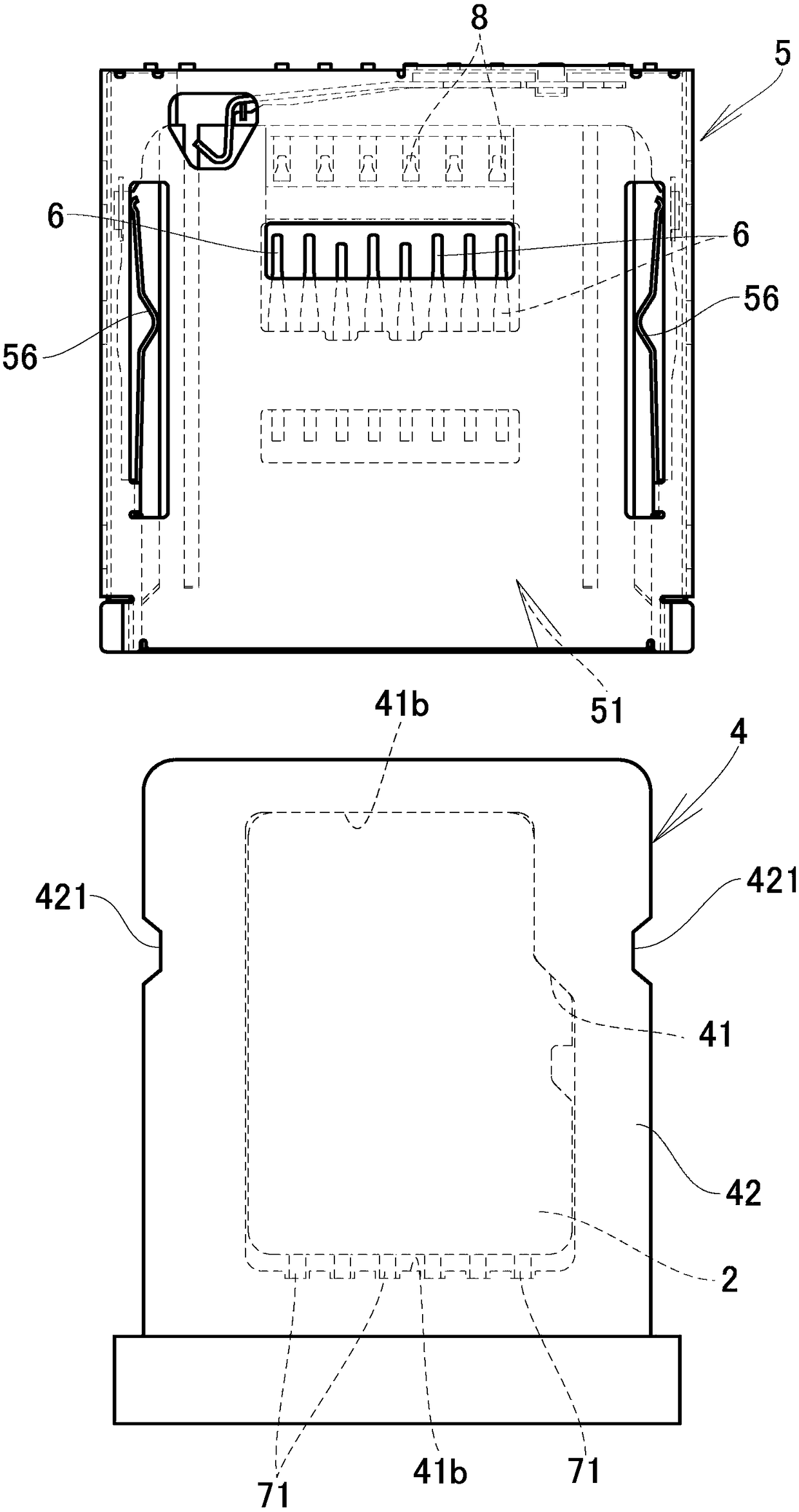
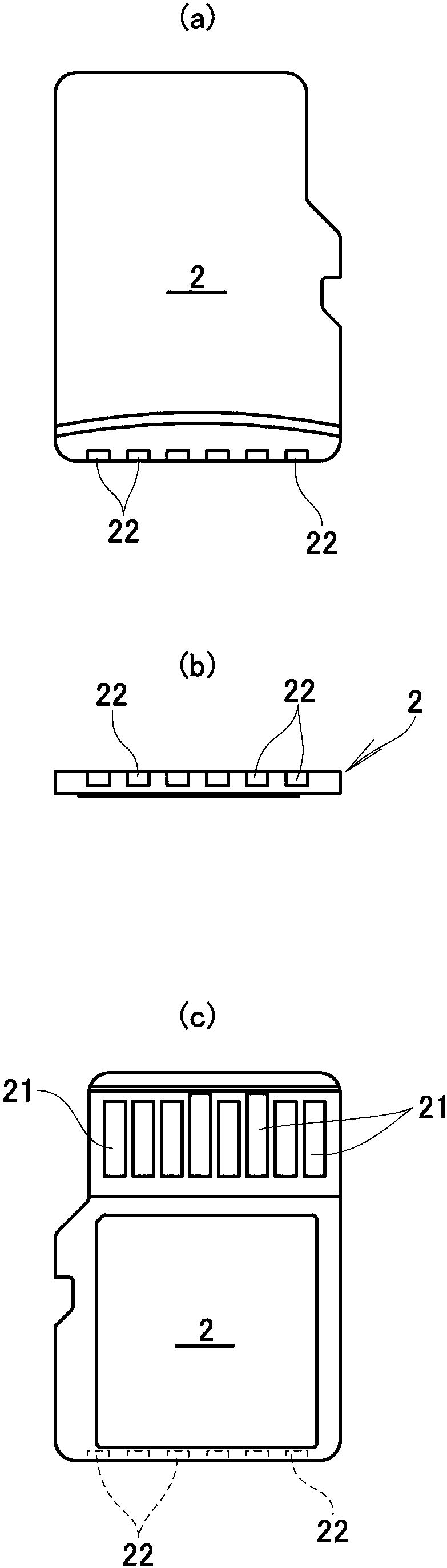
[0036] Next, based on Figure 1 to Figure 5 The illustrated embodiment illustrates an embodiment of the card connector 3 of the invention. In addition, in the figure, reference numeral 1 denotes a substrate, reference numeral 2 denotes a card, and reference numeral 3 denotes a card connector.

[0037] The card 2 is, for example, a composite card having a built-in flash memory, an integrated circuit, etc. (not shown in particular) and having basic functions such as a memory card and other functions such as an IC card.

[0038] Such as image 3 As shown, the card 2 is formed into a thin flat plate shape, and is equipped with a plurality of memory card pads (hereinafter referred to as basic function pads) 21, 21 ... connected to the flash memory, and a plurality of IC card pads connected to the integrated circuit. Pads (hereinafter referred to as other function pads) 22, 22, . . .

[0039] The basic function pads 21, 21, .

[0040] The other functional pads 22, 22... are arra...


PUM


Abstract

The invention provides a card connector which is capable of connection of a composite card integrated with a plurality of functions and is high in degree of freedom of design. The card connector (3) has a card tray (4) which stores a card (2) in a card storage recess (41), a shell (5) having a tray insertion part (51) for the card tray (4) to insert, and a fundamental function contact (6) in contact with fundamental function bonding pads (21, 21...) configured on the surface of the card (2), the card tray has tray built-in contacts (7, 7...) which protrude on an inner surface of the card storage recess (41) and are in contact with other functional bonding pads (22, 22...) configured on an outer circumferential surface of the card (2), and the shell (5) has shell side contacts (8, 8...) incontact with the tray built-in contact (7) when the card tray (4) is inserted in the tray insertion part (51) and can connect the composite card (2) to a substrate (1).

Description

technical field [0001] The present invention relates to a card connector for connecting a card to an electronic device. Background technique [0002] Currently, various types of cards, such as IC cards and flash memory cards, are used as external connection media for mobile electronic terminals such as smartphones. [0003] As a mechanism for connecting such a variety of cards to electronic devices such as smartphones, there are known selectable card connectors (for example, refer to Patent Document 1) equipped with card trays that can appropriately select and accommodate a variety of cards, and multi-layered arrangements. A multilayer card connector having a structure for connecting various cards (for example, refer to Patent Document 2) and the like. [0004] The selectable card connector includes: a card tray capable of appropriately selecting and storing various cards; a housing having a tray insertion portion into which the card tray is inserted; and contacts arranged ...

Claims


Application Information

Patent Timeline
Patent Type & Authority Applications(China)
IPC IPC(8): H01R12/71H01R13/02H01R13/502H01R13/629H01R13/627
CPCH01R12/714H01R12/716H01R13/02H01R13/502H01R13/6275H01R13/629H01R2201/16
Inventor 江尻孝一郎米山一畅近藤晴彦
Owner SMK CO LTD
Why Eureka
Try Eureka