Rapid self-locking type energy-saving strain clamp

A tension clamp and self-locking technology, which is applied in the field of fast self-locking energy-saving tension clamps, can solve the problems of difficult work at heights, tools or parts falling, insufficient self-locking tightening force, etc. The effect of high-altitude work difficulty, easy production and processing, and high safety

Pending Publication Date: 2018-11-13
JIANGSU SHUANGHUI POWER DEV
View PDF1 Cites 0 Cited by
  • Summary
  • Abstract
  • Description
  • Claims
  • Application Information

AI Technical Summary

Problems solved by technology

Therefore, the work at heights requires the cooperation of multiple people, and it is very difficult for workers to work at heights. In addition, this structural design is likely to cause tools or parts to fall from heights during the construction process, which poses a great safety hazard.
[0003] Of course, with the continuous improvement of technology in recent years, some manufacturers have also introduced self-locking tension clamps. For example, the application publication number is CN102361303A, the application publication date is 2012.02. The Chinese patent of the tension clamp discloses a self-locking tension clamp, but its structural design is cumbersome, the production process is complicated, the self-locking fastening force is not enough, and the installation process is also complicated, and human factors directly affect the installation. quality, and there are potential safety hazards

Method used


Image

  • Rapid self-locking type energy-saving strain clamp
  • Rapid self-locking type energy-saving strain clamp
  • Rapid self-locking type energy-saving strain clamp

Examples


Embodiment 1

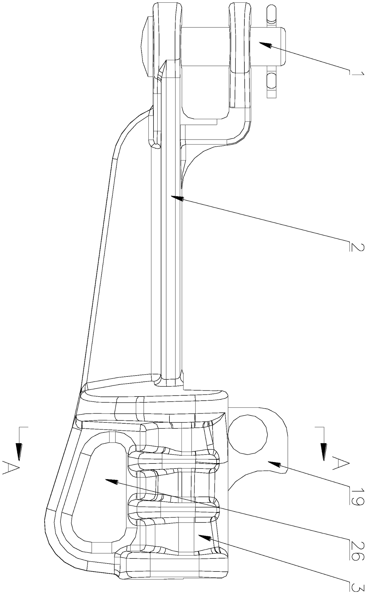
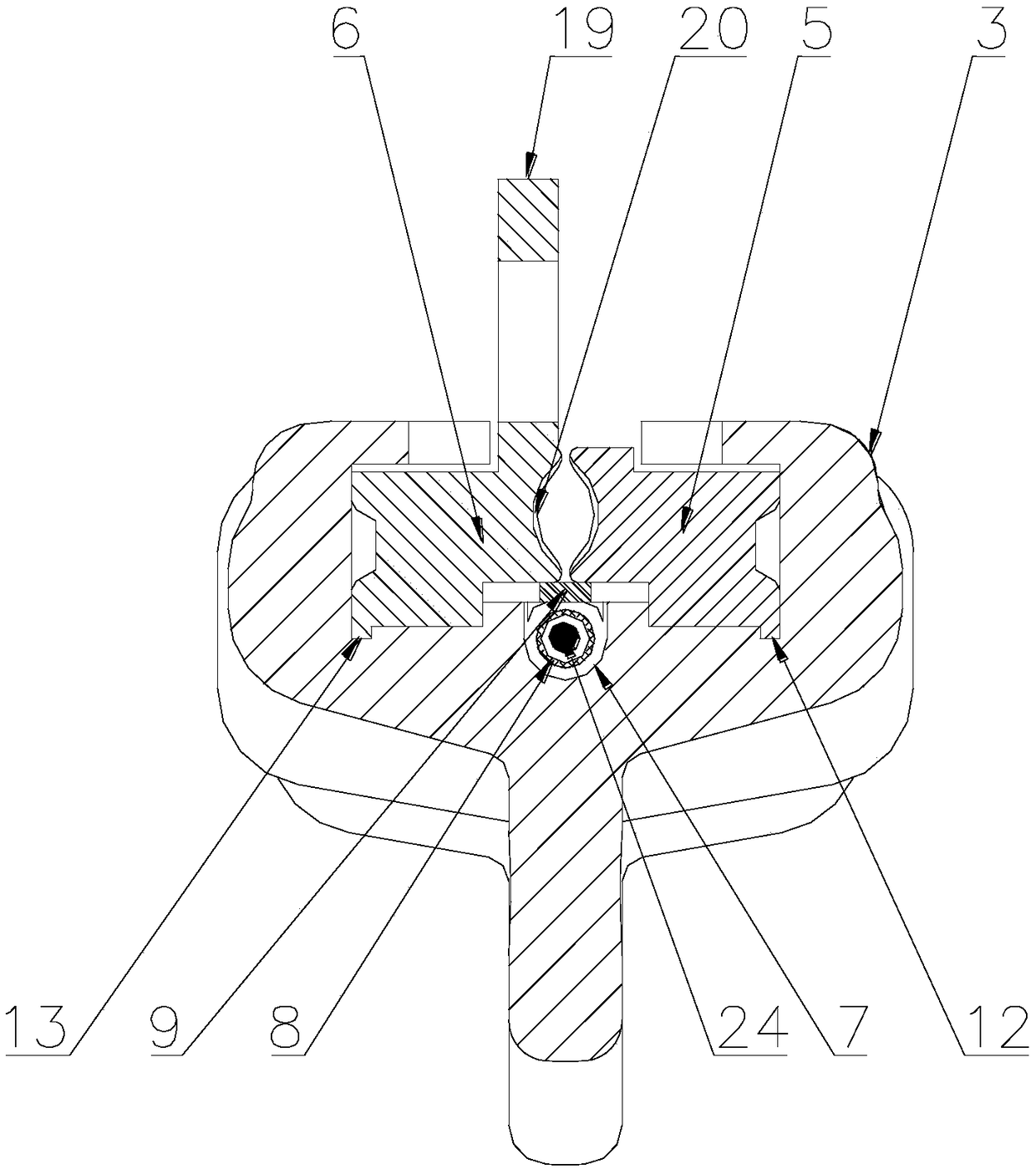
[0049] This embodiment includes a clamp body 3 provided with a latch 1, a connecting rod 2, and a mounting hole 26. The clamp body 3 is provided with wedge-shaped slots with openings at both ends and flash edges on the sides of the slots. Structures are arranged in the wedge-shaped slots. Relatively symmetrical wire clamp I5 and wire clamp II6 that move along the side of the wedge-shaped groove and are wedge-shaped when they are combined; there is a spring movement groove 7 with an arc-shaped cross-section in the middle of the bottom of the wedge-shaped groove. A compression spring 8 is arranged in the movement groove 7, and above the compression spring 8, a spring is laid on the bottom of the wedge-shaped groove to pull the displacement of the compression spring 8 and follow the wire clip I5 and the wire clip. II6 moves and moves the force transmission plate 9 . Instructions attached Figure 15 It is a schematic diagram of the structure of the present invention in a natural ...

Embodiment 2

[0052] As attached in the manual Figure 1-13 As shown, the present embodiment is provided with the clamp body 3 of the bolt 1, the connecting rod 2 and the mounting hole 26. The clamp body 3 is provided with wedge-shaped grooves with openings at both ends and flash edges on the sides of the two grooves. There are wire clip I5 and wire clip II6 with symmetrical structure, moving along the side of the wedge-shaped groove, and the two are wedge-shaped when they are combined; there is a spring movement groove 7 with an arc-shaped cross-section in the middle of the bottom of the wedge-shaped groove , the spring movement groove 7 is provided with a compression spring 8, above the compression spring 8 is laid on the bottom of the wedge-shaped groove, pulling the displacement of the compression spring 8, and following the clamp I5 and the The active force transmission plate 9 that moves when the line clamp II 6 moves.

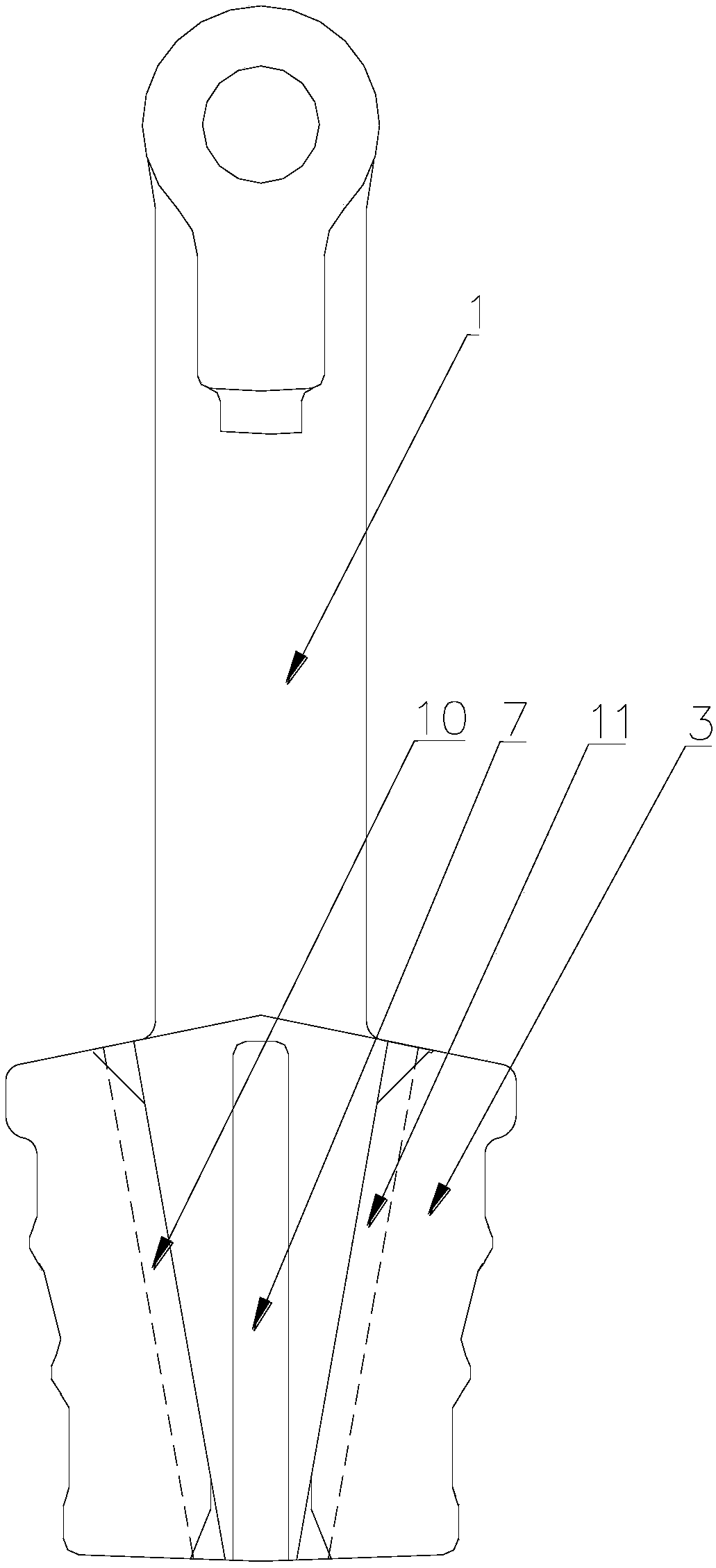
[0053] In this embodiment, groove track I10 and groove track II...

Embodiment 3

[0060] As attached in the manual Figure 1-13 As shown, the present embodiment is provided with the clamp body 3 of the bolt 1, the connecting rod 2 and the mounting hole 26. The clamp body 3 is provided with wedge-shaped grooves with openings at both ends and flash edges on the sides of the two grooves. There are wire clip I5 and wire clip II6 with symmetrical structure, moving along the side of the wedge-shaped groove, and the two are wedge-shaped when they are combined; there is a spring movement groove 7 with an arc-shaped cross-section in the middle of the bottom of the wedge-shaped groove , the spring movement groove 7 is provided with a compression spring 8, above the compression spring 8 is laid on the bottom of the wedge-shaped groove, pulling the displacement of the compression spring 8, and following the clamp I5 and the The active force transmission plate 9 that moves when the line clamp II 6 moves.

[0061] In this embodiment, groove track I10 and groove track II...


PUM


Abstract

The invention discloses a self-locking type energy-saving strain clamp, belongs to the technical field of power equipment, and solves the problems of too many parts, tedious installation, difficulty of high-altitude work and high probability of safety troubles traditionally. The strain clamp comprises a wire clamp body, a wedge groove whose two ends are open and two sides are provided with flashesrespectively is formed in the wire clamp body, and a first wire clamp, a second wire clamp, a spring movement groove, a pressure spring and an active force transfer plate are arranged in the wedge groove. The self-locking type energy-saving strain clamp is ingenious in structural design, a real self-locking function can be realized, and the safety performance is very high; the whole motion can becompleted needless of cooperation among people, bolts and the like are not included, auxiliary tools are not needed, and the difficulty of high-altitude work is reduced greatly; and the self-lockingtype energy-saving strain clamp is simple in structural design, easy to produce and process, and high in practicality and can be widely applied to technical fields of power hardware.

Description

technical field [0001] The invention belongs to the technical field of electric equipment, and in particular relates to a fast self-locking energy-saving tension-resistant clamp. Background technique [0002] The tension clamp is used to fix the wire to bear the tension of the wire, and hang the wire to the metal fitting on the tension string or tower. At present, the bolt-type strain clamp with relatively mature technology is the most widely used, which consists of four pressure plates fastened by several bolts, and the grip is realized by bolt fastening. There are many strain clamp parts in this structure, and auxiliary tools for fastening bolts are required. Therefore, many people are required to cooperate to complete the work at heights, and it is very difficult for workers to work at heights. In addition, this structural design is likely to cause tools or parts to fall from heights during the construction process, which poses a great safety hazard. [0003] Of course,...

Claims


Application Information

Patent Timeline
Patent Type & Authority Applications(China)
IPC IPC(8): H02G7/05
CPCH02G7/056
Inventor 张静华沈啸峰王银春刘成吕刚朱路张聪
Owner JIANGSU SHUANGHUI POWER DEV
Why Eureka
Try Eureka