
Electromagnetic T-shaped beam vibration energy harvester on basis of rigid and flexible combined structure
A vibration energy collection, rigid-flexible technology, applied in electrical components, electromechanical devices, etc., can solve the problem of high resonance frequency, extend the effective length of the beam, and achieve the effect of wireless power supply
- Summary
- Abstract
- Description
- Claims
- Application Information
AI Technical Summary
Problems solved by technology
Method used
Image

Examples
Embodiment Construction
[0023] The present invention will be further described in detail below in conjunction with the accompanying drawings.
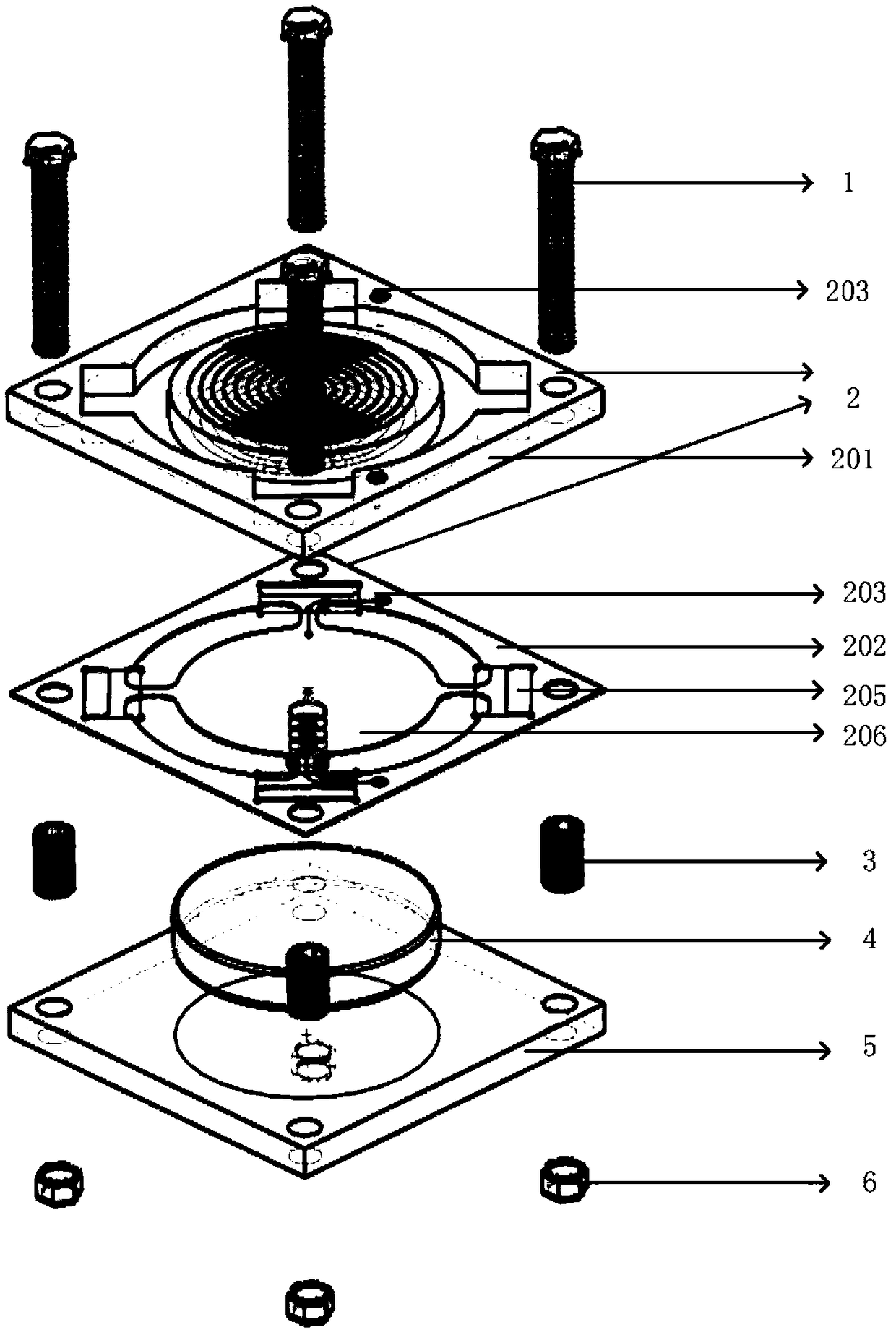
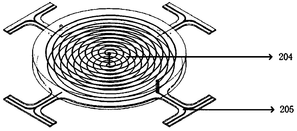
[0024] The present invention provides an electromagnetic T-beam vibration energy harvester based on a rigid-flexible structure, the structure of which is as follows: figure 1 As shown, it includes screw 1, rigid-flex board 2, magnet 4, copper pillar 3, rigid support board 5 and nut 6. Wherein, the rigid-flex board 2 includes a rigid board 201 , a flexible board 202 , a conductive hole 203 , a coil 204 , a T-beam 205 and a pickup piece 206 . The specific structure of the coil in the board is as follows figure 2 As shown, the center of the top coil and the bottom coil are connected by a via hole, and the two coils should be wound in opposite directions during design, so as to ensure that the induced electromotive force generated by the two coils is in the same direction. Both ends of the coil are connected to the flexible board through via holes, and finally...
PUM
 Abstract
Description
Claims
Application Information