Hay chopping and conveying equipment for feeding horses in a horse farm

A technology for conveying equipment and hay, applied in cutting equipment, conveyor objects, applications, etc., can solve the problem of large manpower of breeders

Active Publication Date: 2021-06-15
泗水县圣源土地开发运营有限公司
View PDF7 Cites 0 Cited by
  • Summary
  • Abstract
  • Description
  • Claims
  • Application Information

AI Technical Summary

Problems solved by technology

[0002] When the breeder feeds the horses on the horse farm, he usually needs to manually chop the collected hay, then collect it and put it in the warehouse for storage. When the horses need to be fed, the breeder needs to go to the warehouse to get the hay and pour it Feed in the container for feeding the horses, but to chop the hay and pour it into the container for feeding the horses with hay, the breeder needs to walk back and forth to feed the horses, so the breeder consumes a lot of manpower

Method used


Image

  • Hay chopping and conveying equipment for feeding horses in a horse farm
  • Hay chopping and conveying equipment for feeding horses in a horse farm
  • Hay chopping and conveying equipment for feeding horses in a horse farm

Examples


Embodiment 1

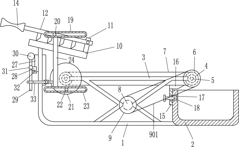
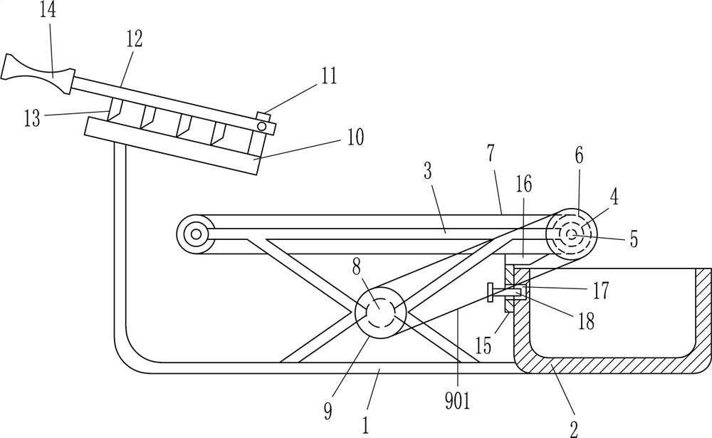
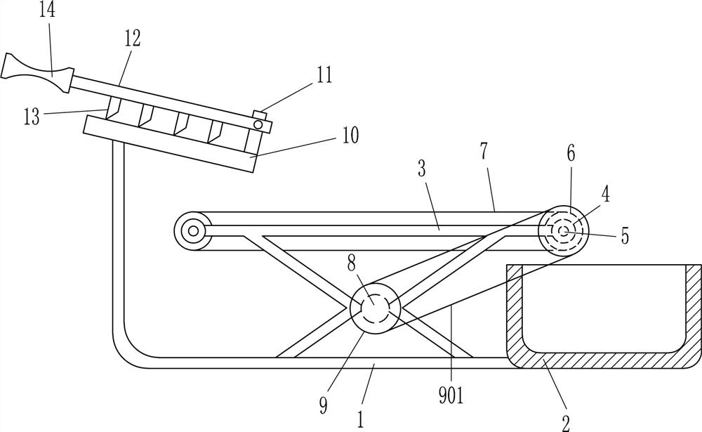
[0023] A kind of hay chopping and conveying equipment for feeding horses in a horse farm, such as Figure 1-5 As shown, it includes a mounting plate 1, a feeding box 2, a mounting frame 3, a bearing seat 4, a rotating rod 5, a conveying wheel 6, a conveyor belt 7, a reduction motor 8, a pulley 9, a flat belt 901, an installation swash plate 10, a fixed Block 11, swing bar 12, strip cutter 13 and handle 14, the right end of mounting plate 1 is connected with feeding box 2, the front and rear sides on the right side of mounting plate 1 top are all connected with mounting frame 3, the left and right sides of mounting frame 3 in the front and rear sides Both ends are connected with bearing seats 4, and the two corresponding front and rear bearing seats 4 are connected with rotating rods 5 with interference, and the middle parts of the rotating rods 5 on the left and right sides are connected with conveying wheels 6, and the conveying wheels 6 are wound around Conveyor belt 7 is ar...

Embodiment 2

[0025] A kind of hay chopping and conveying equipment for feeding horses in a horse farm, such as Figure 1-5 As shown, it includes a mounting plate 1, a feeding box 2, a mounting frame 3, a bearing seat 4, a rotating rod 5, a conveying wheel 6, a conveyor belt 7, a reduction motor 8, a pulley 9, a flat belt 901, an installation swash plate 10, a fixed Block 11, swing bar 12, strip cutter 13 and handle 14, the right end of mounting plate 1 is connected with feeding box 2, the front and rear sides on the right side of mounting plate 1 top are all connected with mounting frame 3, the left and right sides of mounting frame 3 in the front and rear sides Both ends are connected with bearing seats 4, and the two corresponding front and rear bearing seats 4 are connected with rotating rods 5 with interference, and the middle parts of the rotating rods 5 on the left and right sides are connected with conveying wheels 6, and the conveying wheels 6 are wound around Conveyor belt 7 is ar...

Embodiment 3

[0028] A kind of hay chopping and conveying equipment for feeding horses in a horse farm, such as Figure 1-5 As shown, it includes a mounting plate 1, a feeding box 2, a mounting frame 3, a bearing seat 4, a rotating rod 5, a conveying wheel 6, a conveyor belt 7, a reduction motor 8, a pulley 9, a flat belt 901, an installation swash plate 10, a fixed Block 11, swing bar 12, strip cutter 13 and handle 14, the right end of mounting plate 1 is connected with feeding box 2, the front and rear sides on the right side of mounting plate 1 top are all connected with mounting frame 3, the left and right sides of mounting frame 3 in the front and rear sides Both ends are connected with bearing seats 4, and the two corresponding front and rear bearing seats 4 are connected with rotating rods 5 with interference, and the middle parts of the rotating rods 5 on the left and right sides are connected with conveying wheels 6, and the conveying wheels 6 are wound around Conveyor belt 7 is ar...


PUM


Abstract

The invention relates to a conveying device, in particular to a conveying device for crushing hay for feeding horses in a horse farm. Technical problem: To provide a hay chopping conveying equipment for feeding horses in a horse farm that saves manpower and completes chopping hay and facilitates transportation of hay for feeding horses. The technical solution is: a hay chopping conveying equipment for feeding horses in a racecourse, including a mounting plate, a feeding box, a mounting frame, a bearing seat, a rotating rod, a conveying wheel, a conveyor belt, a deceleration motor, a pulley, a flat belt, and an installation ramp plate, fixing block, etc.; the right end of the mounting plate is connected with a feeding box, and the front and rear sides of the top right side of the mounting plate are connected with mounting frames. The present invention manually swings the swing rod up and down to complete the chopping of the hay, and through the clockwise rotation of the reduction motor, the automatic transportation of the chopped hay to the feeding box can be completed to complete the feeding of the horses, and through the process of transportation The clockwise rotation of the rotary lever on the left drives the swing lever to automatically swing up and down to finish chopping hay.

Description

technical field [0001] The invention relates to a conveying device, in particular to a conveying device for crushing hay for feeding horses in a horse farm. Background technique [0002] When the breeder feeds the horses on the horse farm, he usually needs to manually chop the collected hay, then collect it and put it in the warehouse for storage. When the horses need to be fed, the breeder needs to go to the warehouse to get the hay and pour it Feeding is carried out in the container for feeding the horses, but to chopping the hay and pouring it into the container for feeding the horses with hay, the breeder needs to walk back and forth to feed the horses, which consumes a lot of manpower for the breeder. Contents of the invention [0003] In order to overcome the disadvantages in the prior art of manually chopping hay and manually transporting the hay to feed the horses, the technical problem is to provide a horse feeder that saves manpower to complete the chopping of th...

Claims


Application Information

Patent Timeline
Patent Type & Authority Patents(China)
IPC IPC(8): A01F29/08A01F29/09B65G47/16B65G45/12
CPCA01F29/08A01F29/09B65G45/12B65G47/16
Inventor 刘钦鹏
Owner 泗水县圣源土地开发运营有限公司
Why Eureka
Try Eureka