Automatic machining equipment for high-temperature-resistant and high-pressure-resistant valve

A technology of high-pressure valves and processing equipment, applied in the direction of spraying devices, etc., can solve the problems of low efficiency and high labor intensity, and achieve the effect of improving painting efficiency and reducing labor intensity

Pending Publication Date: 2021-11-05
浙江力科阀门有限公司
View PDF4 Cites 0 Cited by
  • Summary
  • Abstract
  • Description
  • Claims
  • Application Information

AI Technical Summary

Problems solved by technology

[0002] Valves are the control components in the fluid delivery system. They have the functions of cut-off, adjustment, flow diversion, reverse flow prevention, pressure stabilization, flow diversion or overflow pressure relief. Valves used in fluid control systems range from the simplest cut-off valve to extremely complex The various valves used in the automatic control system have a wide variety of varieties and specifications. The valves can be used to control the flow of various types of fluids such as air, water, steam, various corrosive media, mud, oil, liquid metal and radioactive media. At the same time, the valve needs to be resistant to high temperature and high pressure, and the valve painting can play a certain protective role for the valve, but the existing valve painting is to spray the outside of the valve by manpower, which has high labor intensity and low efficiency

Method used


Image

  • Automatic machining equipment for high-temperature-resistant and high-pressure-resistant valve
  • Automatic machining equipment for high-temperature-resistant and high-pressure-resistant valve
  • Automatic machining equipment for high-temperature-resistant and high-pressure-resistant valve

Examples


Embodiment Construction

[0017] The following will clearly and completely describe the technical solutions in the embodiments of the present invention with reference to the accompanying drawings in the embodiments of the present invention. Obviously, the described embodiments are only some, not all, embodiments of the present invention. Based on the embodiments of the present invention, all other embodiments obtained by persons of ordinary skill in the art without making creative efforts belong to the protection scope of the present invention.

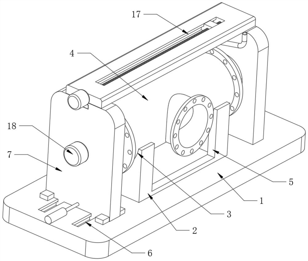
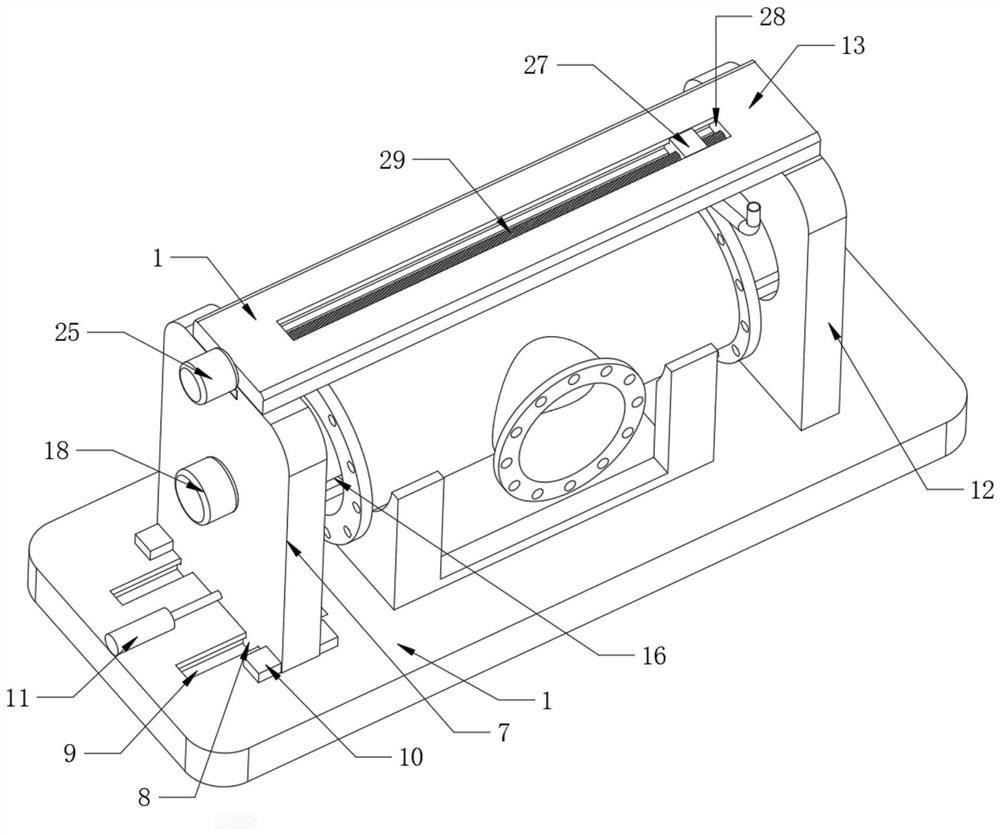
[0018] see Figure 1-Figure 4 , an automatic processing equipment for high-temperature and high-pressure resistant valves in the figure, including a base 1, a placement frame 2 is fixed in the middle of the base 1, a slot 3 is opened in the middle of the placement frame 2, and a valve 4 is placed inside the slot 3 , and the radius of the valve 4 is the same as that of the card slot 3, an anti-interference groove 5 is provided on the end of the placement frame ...


PUM


Abstract

The invention discloses automatic machining equipment for a high-temperature-resistant and high-pressure-resistant valve. The automatic machining equipment comprises a base, a containing frame is fixed to the middle of the base, a clamping groove is formed in the middle of the containing frame, the valve is placed in the clamping groove, the radius of the valve is the same as that of the clamping groove, and an anti-interference groove is formed in the end, close to the clamping groove, of the containing frame. A first hydraulic rod drives a first supporting plate to move in the direction of a first sliding groove, two fixed blocks slide into the valve, the extension end of a second hydraulic rod moves to drive an arc-shaped plate to rotate, the valve is fixed, and a first motor rotates to drive the fixed blocks to rotate. Then, the valve can be driven to overturn. In the overturning process of the valve, the output end of a second motor rotates to drive a spray head to move, complete paint spraying operation on the valve is achieved, automatic paint spraying on the valve is achieved, the paint spraying efficiency on the valve is improved, and the labor intensity of workers is lowered.

Description

technical field [0001] The invention relates to the technical field of production of high-temperature and high-pressure valves, in particular to automatic processing equipment for high-temperature and high-pressure valves. Background technique [0002] Valves are the control components in the fluid delivery system. They have the functions of cut-off, adjustment, flow diversion, reverse flow prevention, pressure stabilization, flow diversion or overflow pressure relief. Valves used in fluid control systems range from the simplest cut-off valve to extremely complex The various valves used in the automatic control system have a wide variety of varieties and specifications. The valves can be used to control the flow of various types of fluids such as air, water, steam, various corrosive media, mud, oil, liquid metal and radioactive media. At the same time, the valve needs to be resistant to high temperature and high pressure, and the valve painting can play a certain protective ...

Claims


Application Information

Patent Timeline
IPC IPC(8): B05B13/02B05B13/04
CPCB05B13/02B05B13/0221B05B13/04
Inventor 胡良建胡天豪吴昌辉
Owner 浙江力科阀门有限公司
Why Eureka
Try Eureka