
Activated carbon processing equipment

A processing equipment and activated carbon technology, applied in the field of activated carbon processing equipment, can solve the problems of uneven heating, large heat loss, large loss of carbonized material, etc., and achieve the effect of reducing heat loss, sufficient heat, and uniform heating

Pending Publication Date: 2022-04-29
安徽久泰新材料科技有限公司 +1
View PDF5 Cites 0 Cited by
  • Summary
  • Abstract
  • Description
  • Claims
  • Application Information

AI Technical Summary

Problems solved by technology

The disadvantages of this activation method are: (1) Due to the high oxygen content in the activation chamber, the activation chamber is still burning continuously in the early stage of activation, resulting in a large loss of carbonized material and a low carbon yield; (2) the temperature in the chamber to be activated The carbonized material can only be retained when the combustion is stopped, but due to insufficient temperature, the activation rate of the carbonized material obtained at this time is low; (3) it is necessary to provide high-temperature steam to the activation chamber, which consumes a lot of energy; and the activation chamber produces Exhaust gas cannot be effectively used, resulting in energy waste
[0005] This external heat rotary high-quality activated carbon high-efficiency, energy-saving and environment-friendly production device has the following deficiencies: (1) only one activation cylinder with a thicker inner diameter is arranged in the rotary activation furnace, and is arranged at the center of the rotary activation furnace, while the activation cylinder The heated annular combustion chamber is arranged on the outer circumference of the activation cylinder, and all the annular combustion chambers are distributed along the axial direction of the activation cylinder at intervals; The heat supply capacity in the center of the cylinder is relatively limited, and the annular combustion chamber is arranged at intervals, and there is also uneven heat supply in the circumferential direction of the activation cylinder; too much carbonized material in the activation cylinder is also prone to In case of uneven heating and insufficient reaction; (2) The activation tail gas generated by the activation reaction needs to be led out of the rotary activation furnace, and after being purified in the activation tail gas recovery combustion system, it can be returned to the annular combustion chamber for combustion to supply heat to the activation cylinder , otherwise it is easy to leak and release a large amount of carbon particles and dust particles; although it also exchanges heat with circulating cooling water to obtain circulating hot water during the extraction process, the heat loss is still relatively large

Method used


Image

  • Activated carbon processing equipment
  • Activated carbon processing equipment
  • Activated carbon processing equipment

Examples


Embodiment Construction

[0057] The technical solution of the present invention will be described in further detail below in conjunction with the accompanying drawings and specific embodiments.

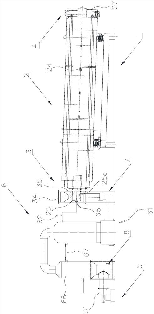
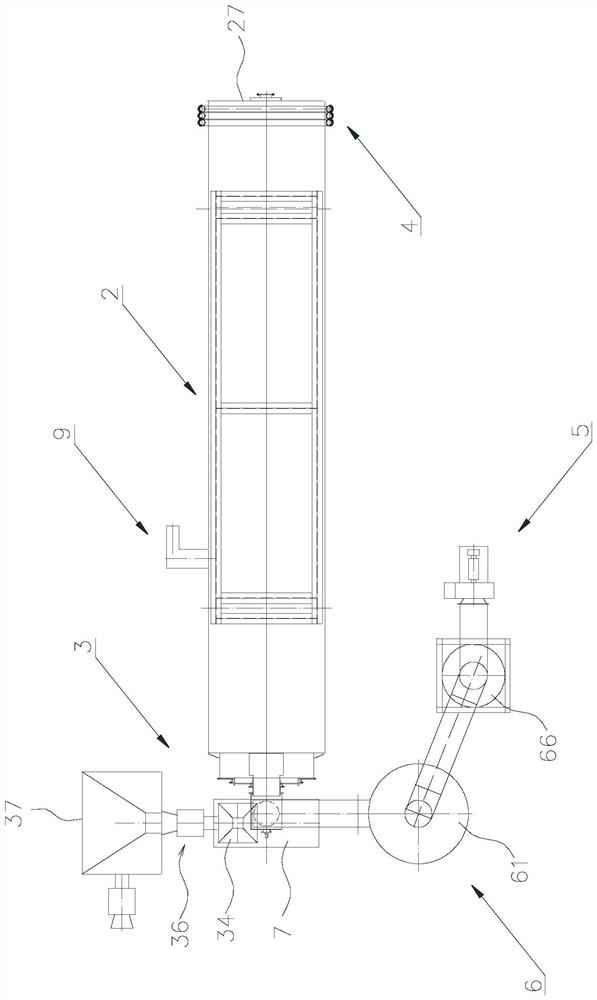
[0058] Such as figure 1 with figure 2 As shown, a kind of activated carbon processing equipment in this embodiment includes a base 1 and an activation furnace 2 arranged on the base 1 through a rotary drive mechanism 9. The activation furnace 2 is inclined downward from the feed end to the discharge end. The two ends of the activation furnace 2 are respectively sealed and installed with a self-feeding device 3 and a discharging device 4.

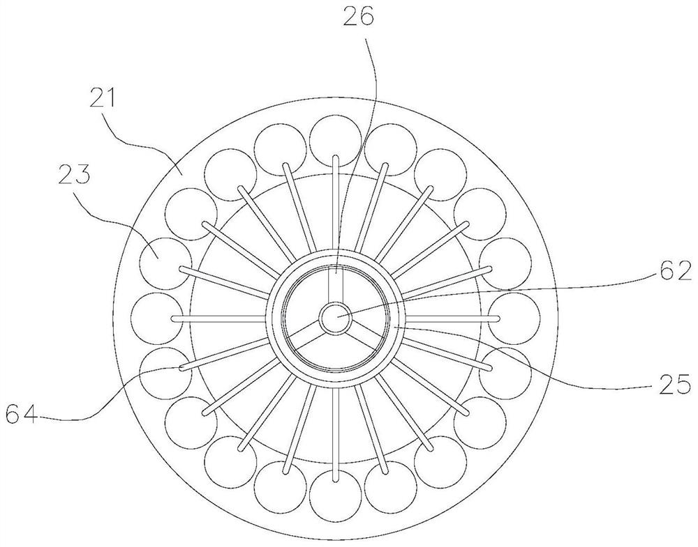
[0059] Such as image 3 with Figure 4 As shown, the activation furnace 2 of the present embodiment includes a furnace body 21, and a combustion chamber 22 and a plurality of activation channels 23 extending axially along the furnace body 21 are formed in the furnace body 21; In the center of the furnace body 21 , the inner diameters of the activation channels 23 are r...


PUM


Abstract

The invention discloses activated carbon processing equipment which comprises an activation furnace, the activation furnace comprises a furnace body, a combustion chamber and an activation channel are formed in the furnace body, and the activation channel is communicated with the combustion chamber at the discharge end of the activation channel; a negative pressure suction device communicated with the combustion chamber is arranged at the feeding end of the furnace body, an air inlet communicated with the combustion chamber is formed in the furnace body, and the negative pressure suction device is used for sucking air and activated tail gas generated in the activation channels into the combustion chamber to be combusted and release heat so as to supply heat to the activation channels. According to the invention, the negative pressure suction device communicated with the combustion chamber is arranged at the feeding end of the activation furnace, so that the activated tail gas and high-temperature flue gas generated by combustion of the activated tail gas cannot escape from the activation furnace under the negative pressure suction, and can be directly utilized in the activation furnace without being led out for purification, and the heat loss is greatly reduced.

Description

technical field [0001] The invention belongs to the technical field of activated carbon production, and in particular relates to activated carbon processing equipment. Background technique [0002] According to different heating methods, activated carbon activation equipment can be divided into two types: internal heating type and external heating type. Among them, the traditional internal heat activation equipment burns the raw material and passes it into high-temperature steam to convert the raw material into carbonized material. The main chemical reaction is: C+HO 2 +O 2 →CO 2 +H 2 . The disadvantages of this activation method are: (1) Due to the high oxygen content in the activation chamber, the activation chamber is still burning continuously in the early stage of activation, resulting in a large loss of carbonized material and a low carbon yield; (2) the temperature in the chamber to be activated The carbonized material can only be retained when the combustion is ...

Claims


Application Information

Patent Timeline
Patent Type & Authority Applications(China)
IPC IPC(8): C01B32/39
CPCC01B32/39
Inventor 章水根
Owner 安徽久泰新材料科技有限公司
Learn More