Hot-fin heater exchanger

A heat exchanger and heat fin technology, applied in the field of heat fin plate heat exchanger and heat exchanger, can solve the problems of inability to withstand high temperature, high pressure, difficult space layout, large volume, etc., and achieve low cost and large heat transfer area. , the effect of small size

Inactive Publication Date: 2002-10-16
NANJING UNIV OF TECH
View PDF0 Cites 10 Cited by
  • Summary
  • Abstract
  • Description
  • Claims
  • Application Information

AI Technical Summary

Problems solved by technology

[0002] Existing large-scale air-conditioning systems, such as subway central air-conditioning systems, large-scale building central air-conditioning systems, and large-scale factory central air-conditioning systems, consider that the allowable pressure drop of the wind is very small, and adopt cross-flow plate-fin heat exchangers, which have low efficiency. , the disadvantages of large volume, light weight, and difficult space layout
The high-temperature flue gas waste heat recovery device adopts a heat pipe heat exchanger, which is large in size, high in cost, and difficult in space layout. It is made of copper and aluminum, which cannot withstand high temperature and high pressure, and is easy to corrode

Method used


Image

  • Hot-fin heater exchanger
  • Hot-fin heater exchanger
  • Hot-fin heater exchanger

Examples


Embodiment Construction

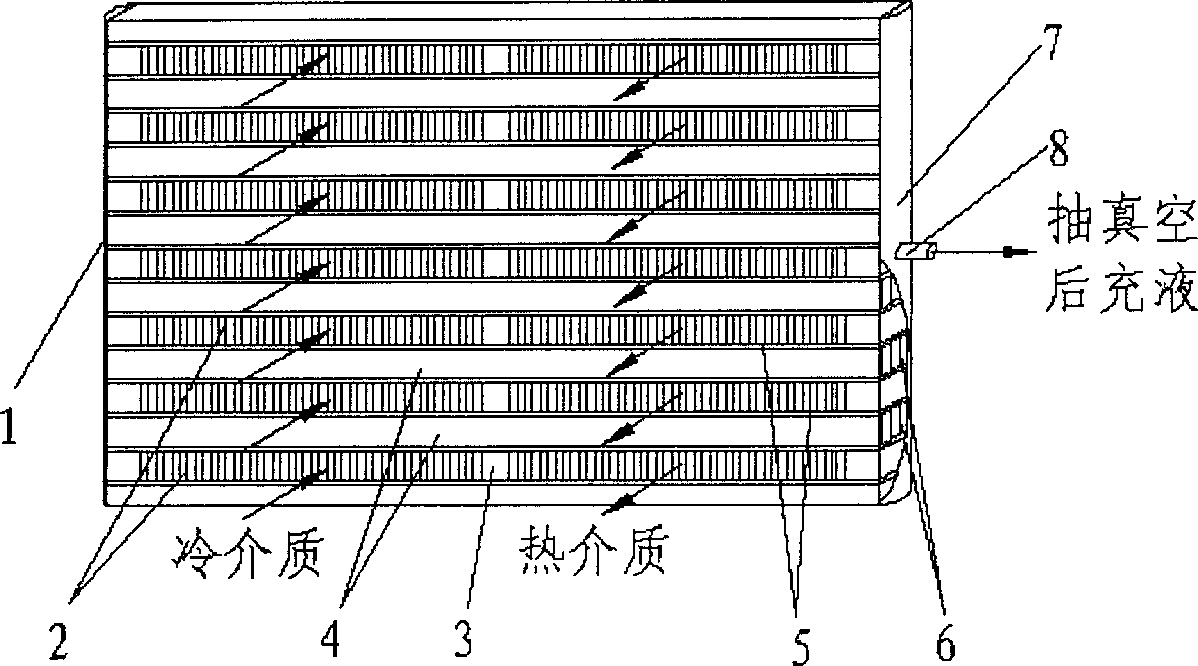
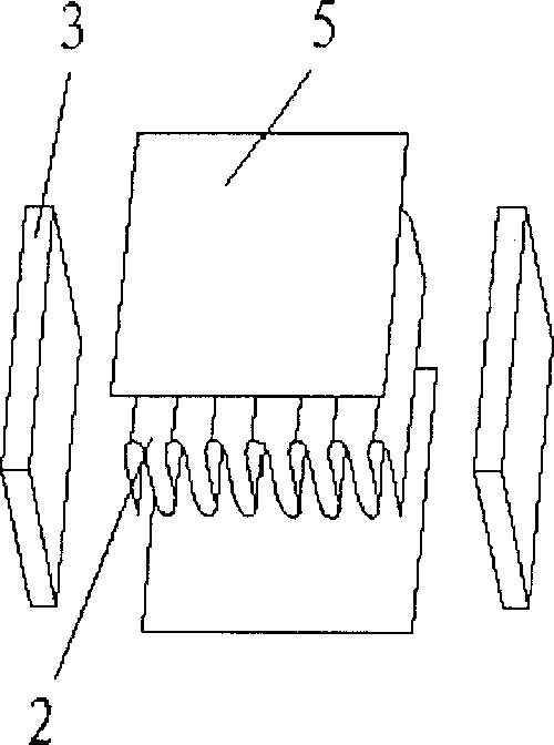
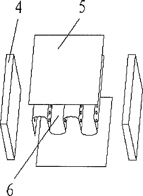
[0013] Refer to attached Figure 1-6 , The main structure of the hot-fin plate heat exchanger has two parts: the head 1, 7 and the core. The heads 1 and 7 are arranged on both sides of the vacuum liquid-filled channel, and one side of the head 7 is provided with a connecting pipe 8 for vacuumizing the vacuum liquid-filled channel and filling it with working liquid. The core body is made of several plate-fin channels and vacuum liquid-filled channels stacked at intervals and vacuum brazed. The plate-fin channel is provided with partitions 5 up and down, seals 3 are provided on both sides, and fins 2 are provided in the channel. Each plate-fin channel is divided into two juxtaposed hot medium channels and cold medium channels by a strip 3 to realize the countercurrent flow of hot fluid and cold fluid. Both the hot medium channel and the cold medium channel have fins, and the upper and lower sides of the fins 2 are provided with partitions 5 (sealed partitions), and the sides o...


PUM


Abstract

The hot finned plate heat exchanger as one new type of heat exchanger is one important mechanism for recovering exhausted wind energy of large air conditioning system, recovering afterheat of high temperature fume and dissipating heat of computer CPU. Its structure includes vacuum liquid-filled end plates and core body, the vacuum liquid-filled end plates are set on two sides of the vacuum liquid-filled passage, and the core body sonsists of the vacuum liquid-filled passage and several finned plate passages. Each of the vacuum liquid-filled passages and the finned plate passages has upper andlower partition boards, side sealing tapes and internal fins. Each of the finned plate passages is separated by one sealing tapes into two parallel hot medium passage and one cold medium passage. After being assembled, the heat exchanger is arranged obliquely or vertically.

Description

technical field [0001] The hot fin plate heat exchanger of the invention relates to a novel heat exchanger, which is an important device for recovering exhaust energy of a large-scale air-conditioning system, recovering residual heat from high-temperature flue gas, and dissipating heat from a computer CPU. Background technique [0002] Existing large-scale air-conditioning systems, such as subway central air-conditioning systems, large-scale building central air-conditioning systems, and large-scale factory central air-conditioning systems, consider that the allowable pressure drop of the wind is very small, and adopt cross-flow plate-fin heat exchangers, which have low efficiency. , The disadvantages of large volume, light weight, and difficult space layout. The high-temperature flue gas waste heat recovery device uses a heat pipe heat exchanger, which is large in size, high in cost, and difficult in space layout. It is made of copper and aluminum, which cannot withstand hi...

Claims


Application Information

Patent Timeline
Patent Type & Authority Applications(China)
IPC IPC(8): G06F1/20H01L23/34
Inventor 凌祥周帼彦虞斌涂善东
Owner NANJING UNIV OF TECH
Why Eureka
Try Eureka