Storage shoe cabinet with variable inner space
An internal space and variable technology, which is applied in the field of shoe storage cabinets, can solve the problems of complex placement procedures and low space utilization of deep boots, and achieves the effects of solving complex placement procedures, simple structures and ingenious designs.
- Summary
- Abstract
- Description
- Claims
- Application Information
AI Technical Summary
Problems solved by technology
Method used
Image

Examples
Embodiment Construction
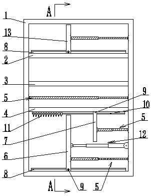
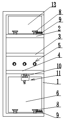
[0022] The storage shoe cabinet with a variable internal space is composed of a cabinet body 1, a partition board A2, a partition board B3, a partition board C4, a movable partition rod 5, a spacer slide plate A6, and a spacer slide plate B7 (see the appendix figure 1 ).
[0023] The partition board A2, the partition board B3 and the partition board C4 are fixedly installed in the cabinet body 1 through intervals; the front end of the cabinet body 1 is hinged with a cabinet door.
[0024] The height between partition plate C4 and the bottom plate of cabinet body 1 corresponds to the height of deep boots; the height between partition plate A2 and the top plate of cabinet body 1 corresponds to the height of high-top shoes; The height between the partitions B3 corresponds to the height of the low top shoes.
[0025] The purpose of such setting is: to place the deep boots in the cabinet body 1 below the partition board C4 during use; the high-top shoes are placed on the partition...
PUM
 Abstract
Description
Claims
Application Information
 - R&D
- Intellectual Property
- Life Sciences
- Materials
- Tech Scout
- Unparalleled Data Quality
- Higher Quality Content
- 60% Fewer Hallucinations
Browse by: Latest US Patents, China's latest patents, Technical Efficacy Thesaurus, Application Domain, Technology Topic, Popular Technical Reports.
© 2025 PatSnap. All rights reserved.Legal|Privacy policy|Modern Slavery Act Transparency Statement|Sitemap|About US| Contact US: help@patsnap.com