

Lifting type drawing display rack used for architectural engineering
A kind of construction engineering and lifting technology, which is applied in the field of display racks, can solve the problems that affect people's viewing of drawings, the table is inconvenient to view drawings, and drawings are easy to be blown away by the wind, etc., so as to achieve the effect of convenient use
- Summary
- Abstract
- Description
- Claims
- Application Information
AI Technical Summary
Problems solved by technology
Method used
Image


Examples
Embodiment 1
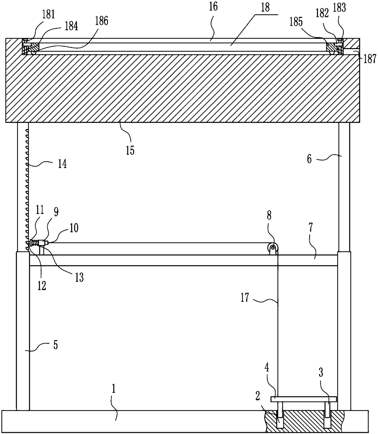
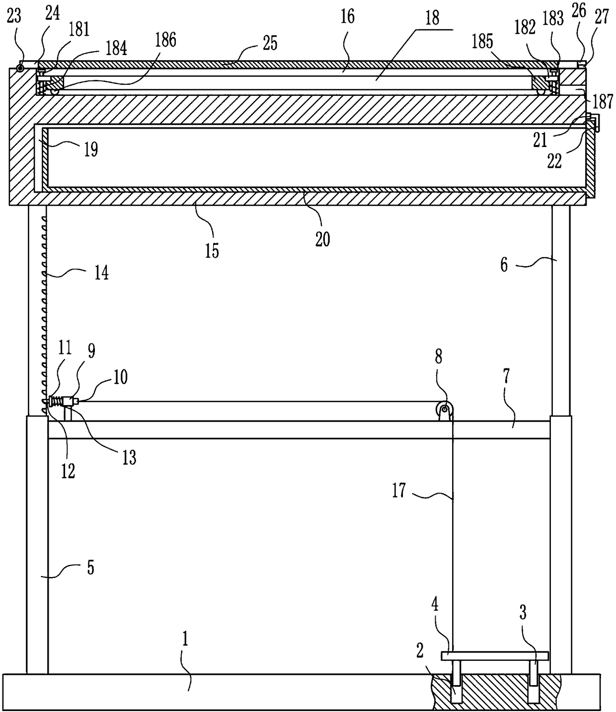
[0020] A lifting type drawing display stand for construction engineering, such as Figure 1-3 As shown, it includes a bottom plate 1, a guide rod 3, a pedal 4, a sleeve 5, a movable rod 6, a cross bar 7, a pulley 8, a first guide sleeve 9, a slide rod 10, a fixed plate 11, a latch 12, a first Spring 13, top plate 15 and backguy wire 17, bottom plate 1 top left and right sides are symmetrically equipped with sleeve 5, and movable rod 6 is arranged in sleeve 5, top plate 15 is installed between left and right sides movable rod 6 tops, top plate 15 There is a placement groove 16 in the middle of the top, and jacks 14 are evenly spaced on the right side of the left side movable rod 6, and a crossbar is installed between the top of the left side of the left sleeve 5 and the top of the left side of the right sleeve 5. Bar 7, pulley 8 is installed on the top right side of cross bar 7, the first guide sleeve 9 is installed on the left side of cross bar 7 top, is provided with slide ba...
Embodiment 2
[0022] A lifting type drawing display stand for construction engineering, such as Figure 1-3 As shown, it includes a bottom plate 1, a guide rod 3, a pedal 4, a sleeve 5, a movable rod 6, a cross bar 7, a pulley 8, a first guide sleeve 9, a slide rod 10, a fixed plate 11, a latch 12, a first Spring 13, top plate 15 and backguy wire 17, bottom plate 1 top left and right sides are symmetrically equipped with sleeve 5, and movable rod 6 is arranged in sleeve 5, top plate 15 is installed between left and right sides movable rod 6 tops, top plate 15 There is a placement groove 16 in the middle of the top, and jacks 14 are evenly spaced on the right side of the left side movable rod 6, and a crossbar is installed between the top of the left side of the left sleeve 5 and the top of the left side of the right sleeve 5. Bar 7, pulley 8 is installed on the top right side of cross bar 7, the first guide sleeve 9 is installed on the left side of cross bar 7 top, is provided with slide ba...
Embodiment 3
[0025] A lifting type drawing display stand for construction engineering, such as Figure 1-3 As shown, it includes a bottom plate 1, a guide rod 3, a pedal 4, a sleeve 5, a movable rod 6, a cross bar 7, a pulley 8, a first guide sleeve 9, a slide rod 10, a fixed plate 11, a latch 12, a first Spring 13, top plate 15 and backguy wire 17, bottom plate 1 top left and right sides are symmetrically equipped with sleeve 5, and movable rod 6 is arranged in sleeve 5, top plate 15 is installed between left and right sides movable rod 6 tops, top plate 15 There is a placement groove 16 in the middle of the top, and jacks 14 are evenly spaced on the right side of the left side movable rod 6, and a crossbar is installed between the top of the left side of the left sleeve 5 and the top of the left side of the right sleeve 5. Bar 7, pulley 8 is installed on the top right side of cross bar 7, the first guide sleeve 9 is installed on the left side of cross bar 7 top, is provided with slide ba...
PUM
 Abstract
Description
Claims
Application Information