Selling rack for textiles

A technology for textiles and sales racks, which is applied to display hangers, display shelves, display stands, etc., which can solve the problems of increased cleaning workload, inconvenient textile display, and poor display effect, achieve good dust-proof effect, and increase viewing and promotion effect of effect

Inactive Publication Date: 2018-11-16
SUZHOU AILIFANG CLOTHES CO LTD
View PDF0 Cites 3 Cited by
  • Summary
  • Abstract
  • Description
  • Claims
  • Application Information

AI Technical Summary

Problems solved by technology

[0002] The original meaning of textile is taken from the general term of spinning and weaving, but with the continuous development and improvement of the textile knowledge system and subject system, especially after the emergence of non-woven textile materials and three-dimensional composite weaving technologies, the current textile is not only a traditional Hand spinning and weaving also include clothing, industrial and decorative textiles produced by non-woven technology, modern three-dimensional weaving technology, and modern electrostatic nano-netting technology. Therefore, modern textile refers to a kind of fiber or fiber collection. The integrated multi-scale structure processing technology requires the use of textile sales racks to display textiles when selling textiles. However, when displaying textiles, the existing textile sales racks cannot display textiles from multiple angles, and they cannot be placed for a long time. Displaying outside is easy to cause dust accumulation, increases the cleaning workload, is inconvenient for the display of textiles, and the display effect is poor, which is not conducive to the promotion of textiles. For this reason, we provide a textile sales rack

Method used


Image

  • Selling rack for textiles
  • Selling rack for textiles
  • Selling rack for textiles

Examples


Embodiment Construction

[0017] The preferred embodiments of the present invention will be described below in conjunction with the accompanying drawings. It should be understood that the preferred embodiments described here are only used to illustrate and explain the present invention, and are not intended to limit the present invention.

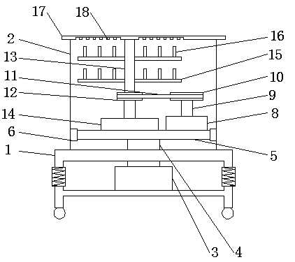
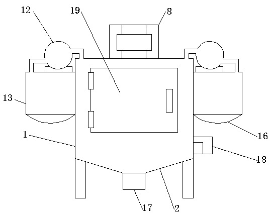
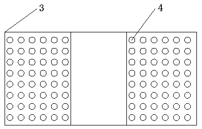
[0018] like Figure 1-3 As shown, it includes a shock-absorbing support 1, the top of which is provided with a storage box 2 for storing textile racks, and a hydraulic power unit 3 is provided at the center of the inner side of the shock-absorbing support 1 as a textile rack. The power source extended or stored in the storage box 2, the top of the hydraulic power device 3 is connected to the hydraulic rod 4, and the top of the hydraulic rod 4 runs through the top center of the shock absorbing bracket 1 and is connected to the bottom center of the storage box 2 for support The central position of the bottom of the plate 5 is used to support and fix the stepper motor ...


PUM


Abstract

The invention relates to a selling rack for textiles. For the selling rack for textiles, a storage box is arranged on the top of a damping bracket, a hydraulic power device is arranged at the centralposition of the inner side of the damping bracket, a hydraulic rod is connected to the top of the hydraulic power device, the top of the hydraulic rod penetrates through the central position of the top of the damping bracket and the central position of the bottom of the storage box to be connected with the central position of the bottom of the support plate, two sides of the support plate are connected with two side walls of the storage box through slider and sliding chute structures, a stepping motor is arranged on one side of the support plate, a textile placing rack can freely stretch out or be stored in the storage box according to the demands, so that the textile placing rack is stable during height adjustment, therefore, the light supplementing work can be carried out during the displaying process, then the ornamental and promotional effects of the textiles are increased, meanwhile, a good dust prevention effect is achieved, the textile placing rack can rotate at 360 degrees, therefore, consumers can observe the textiles in details from multiple aspects, and finally, the sale quantity of the textiles is favorably improved.

Description

technical field [0001] The invention relates to a textile sales rack, which belongs to the technical field of textile sales. Background technique [0002] The original meaning of textile is taken from the general term of spinning and weaving, but with the continuous development and improvement of the textile knowledge system and subject system, especially after the emergence of non-woven textile materials and three-dimensional composite weaving technologies, the current textile is not only a traditional Hand spinning and weaving also include clothing, industrial and decorative textiles produced by non-woven technology, modern three-dimensional weaving technology, and modern electrostatic nano-netting technology. Therefore, modern textile refers to a kind of fiber or fiber collection. The integrated multi-scale structure processing technology requires the use of textile sales racks to display textiles when selling textiles. However, when displaying textiles, the existing text...

Claims


Application Information

Patent Timeline
Patent Type & Authority Applications(China)
IPC IPC(8): A47F7/16A47F11/10A47F5/025
CPCA47F7/166A47F5/025A47F11/10
Inventor 费芬芳卜凯
Owner SUZHOU AILIFANG CLOTHES CO LTD
Why Eureka
Try Eureka