Supporting base of lathe for two-end-face floating positioning of machined part and using method thereof

A technology of workpiece and floating positioning, which is applied in the direction of metal processing machinery parts, positioning devices, metal processing equipment, etc., can solve the problems of obvious vibration knife lines, high production cost, and affect the surface quality of parts, so as to achieve the disappearance of vibration knife lines , the effect of meeting the processing requirements

Pending Publication Date: 2018-11-16
XIAN FASHITE AUTOMOBILE TRANSMISSION CO LTD
View PDF0 Cites 0 Cited by
  • Summary
  • Abstract
  • Description
  • Claims
  • Application Information

AI Technical Summary

Problems solved by technology

[0002] When processing most special-shaped parts with a ratio of large and small diameters greater than 3, the processing requirements can be met by positioning the small end face (first end face) during turning, but it is easy to make the large end face (second end face) of the entire part in a cantilever state; For gears with a diameter ratio greater than 3 between the large and small end faces, when finishing the end face, in order to ensure that the positioning surface is consistent with the spline drawing process, the small end face is always positioned, so that when the large end face is finished, the vibrating knife pattern is obvious, affecting the surface of the part quality
[0003] In the prior art, most gear manufacturers use imported double-end hydraulic floating positioning fixtures for double-end positioning, but the manufacturing cost of this kind of fixture is relatively high

Method used


Image

  • Supporting base of lathe for two-end-face floating positioning of machined part and using method thereof
  • Supporting base of lathe for two-end-face floating positioning of machined part and using method thereof
  • Supporting base of lathe for two-end-face floating positioning of machined part and using method thereof

Examples


Embodiment Construction

[0037] The present invention is described in further detail below in conjunction with accompanying drawing:

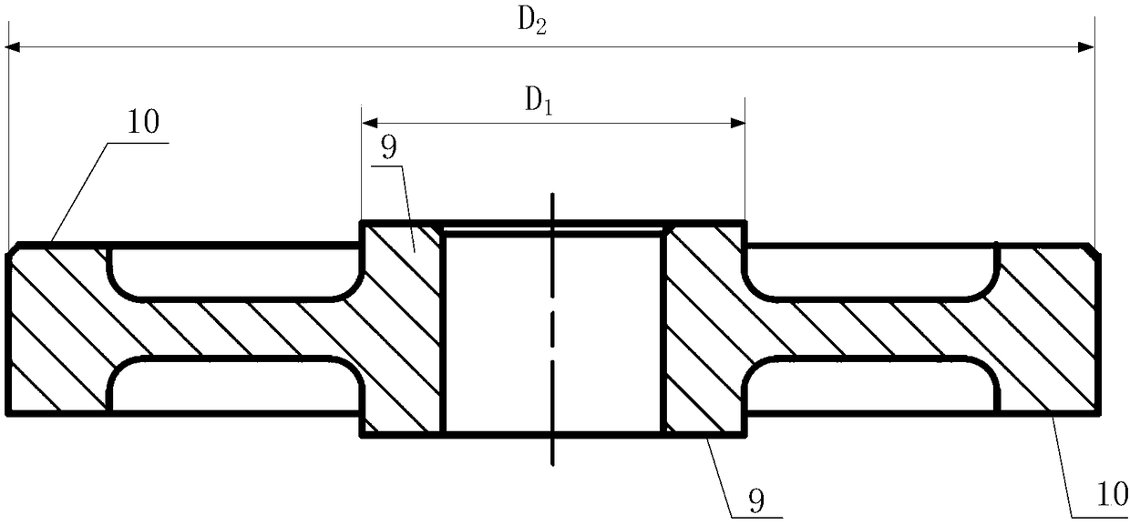
[0038] see figure 1 , the workpiece 20 of the present invention is a special-shaped part, and the special-shaped part is a part whose diameter ratio between the second and first end faces is greater than 3. In this embodiment, it is a gear, and the second end face 10 is a tooth portion close to the gear on the two end faces The first end surface 9 is a support surface close to the gear axis on both end surfaces; the first end surface 9 and the second end surface 10 have a height difference within a certain range; the diameter of the second end surface 10 is D 2 , the diameter of the first end face 9 is D 1 ,D 2 / D 1 >3; In this embodiment, both ends of the gear are provided with weight-reducing grooves.

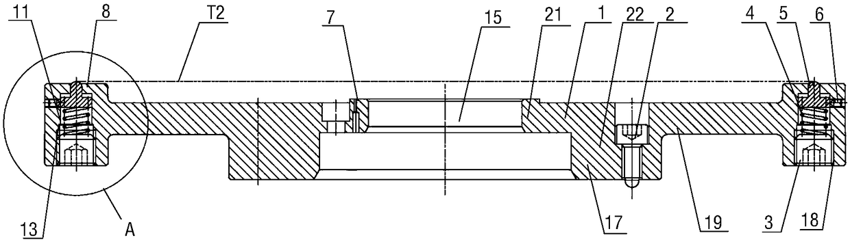
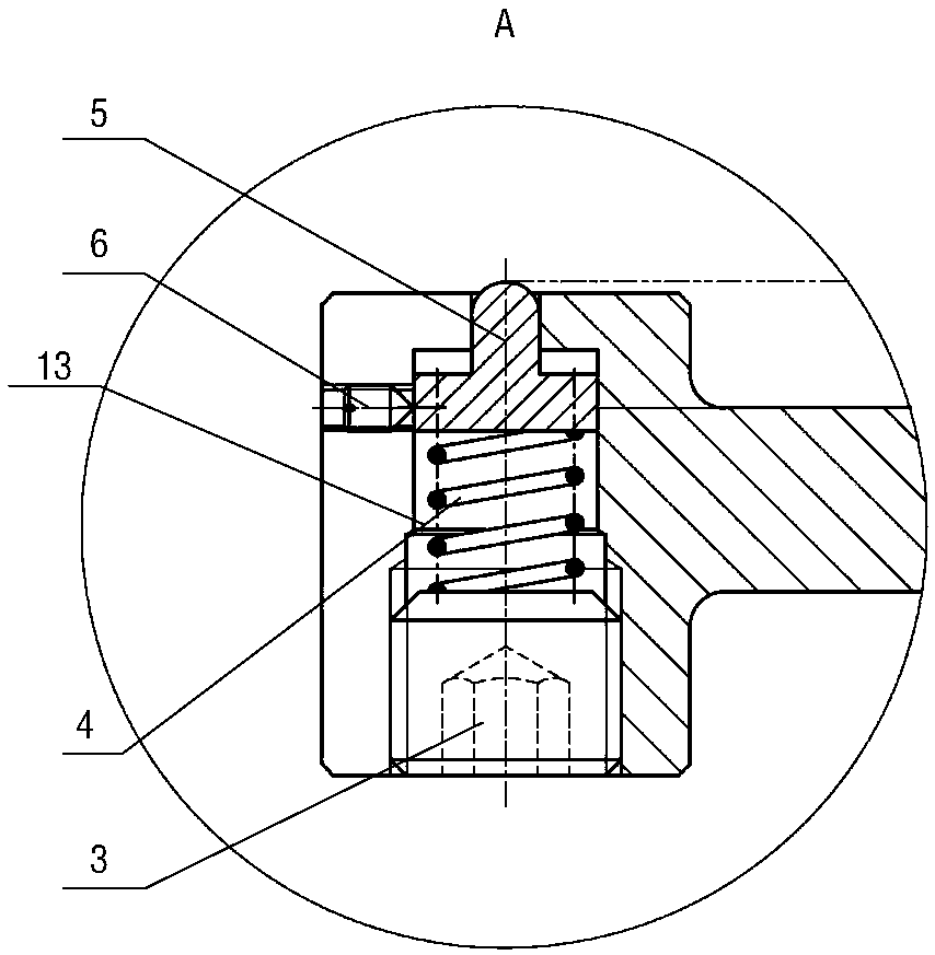
[0039] see figure 2 with image 3, the support seat entity 1 of the present invention includes a mounting hole 15, an inner ring 17 and an outer ring 18; the i...


PUM


Abstract

The invention discloses a supporting base of a lathe for two-end-face floating positioning of a machined part and a using method of the supporting base. The supporting base is provided with a supporting base solid body, a floating supporting mechanism is arranged in the supporting base solid body, therefore, when the supporting base supports and positions the first end face of the machined part, the floating supporting mechanism is added and used for carrying out floating supporting on the second end face of the special-shaped part for assisting, and the second end face and the first end faceof the machined part has the height difference within the certain range. Since the first end face is precisely positioned, and the second end face is supported in a floating mode, it can be ensured that the first end face is firmly positioned, the second end face always makes close contact with a clamp, it is ensured that the second end face of the part is not in a suspended state in the machiningprocess, the turned position of the second end face is smooth and flat, and vibration knife lines disappear.

Description

technical field [0001] The invention relates to the technical field of support mechanisms, in particular to a support seat for floating and positioning a workpiece with double ends of a lathe and a method for using the same. Background technique [0002] When processing most special-shaped parts with a ratio of large and small diameters greater than 3, the processing requirements can be met by positioning the small end face (first end face) during turning, but it is easy to make the large end face (second end face) of the entire part in a cantilever state; For gears with a diameter ratio greater than 3 between the large and small end faces, when finishing the end face, in order to ensure that the positioning surface is consistent with the spline drawing process, the small end face is always positioned, so that when the large end face is finished, the vibrating knife pattern is obvious, affecting the surface of the part quality. [0003] In the prior art, most gear manufactu...

Claims


Application Information

Patent Timeline
Patent Type & Authority Applications(China)
IPC IPC(8): B23Q3/00
CPCB23Q3/00
Inventor 柯昌全
Owner XIAN FASHITE AUTOMOBILE TRANSMISSION CO LTD
Why Eureka
Try Eureka