
Automatic cutting and receiving auxiliary device for labels

An auxiliary device and automatic technology, applied in the direction of metal processing, etc., can solve the problems of labels left on the ground, poor collection efficiency, and too simple structure, so as to achieve vibration effect, save storage space, and facilitate practical use Effect

Pending Publication Date: 2018-11-16
苏州利通印刷有限公司
View PDF0 Cites 0 Cited by
  • Summary
  • Abstract
  • Description
  • Claims
  • Application Information

AI Technical Summary

Problems solved by technology

[0002] Labels for electronic products are printed materials used to identify the relevant instructions of electronic products, and most of them are self-adhesive on the back. There is also a self-adhesive label. In the production and processing of electronic products, a large number of them are often used Labels, in order to ensure large-scale production efficiency, often use automated equipment to print labels, and the cost of forming is often that multiple labels are glued together, in the shape of strips or blocks, and some cutting equipment is required to cut them. After cutting, the material is often collected manually, and the efficiency of the material is not good. Some auxiliary devices are needed, but the structure of this type of auxiliary device is too simple, and specific operations need to be performed manually. It is necessary to control the cutting efficiency, and even during the receiving process, the cutting equipment will be suspended. Moreover, during the entire receiving process, the labels are often left on the ground, which increases the defective rate and brings a lot of trouble to the factory. certain economic loss

Method used

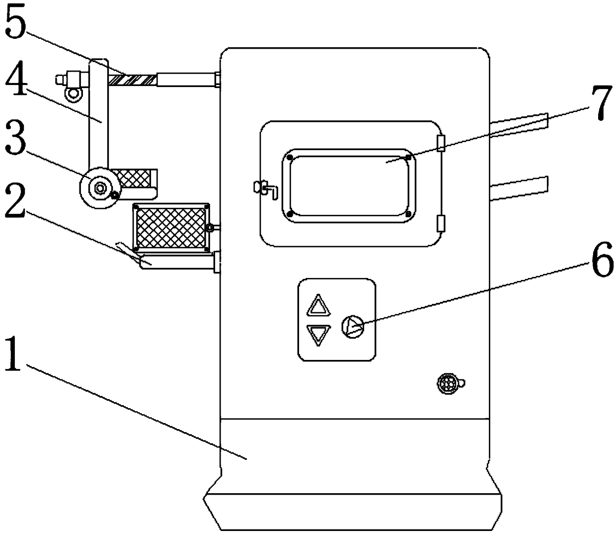

Image

  • Automatic cutting and receiving auxiliary device for labels
  • Automatic cutting and receiving auxiliary device for labels
  • Automatic cutting and receiving auxiliary device for labels

Examples


Embodiment Construction

[0019] The following will clearly and completely describe the technical solutions in the embodiments of the present invention with reference to the accompanying drawings in the embodiments of the present invention. Obviously, the described embodiments are only some, not all, embodiments of the present invention. Based on the embodiments of the present invention, all other embodiments obtained by persons of ordinary skill in the art without making creative efforts belong to the protection scope of the present invention.

[0020] In the description of the present invention, it should be noted that the terms "upper", "lower", "inner", "outer", "front end", "rear end", "both ends", "one end", "another end" The orientation or positional relationship indicated by etc. is based on the orientation or positional relationship shown in the drawings, and is only for the convenience of describing the present invention and simplifying the description, rather than indicating or implying that ...


PUM


Abstract

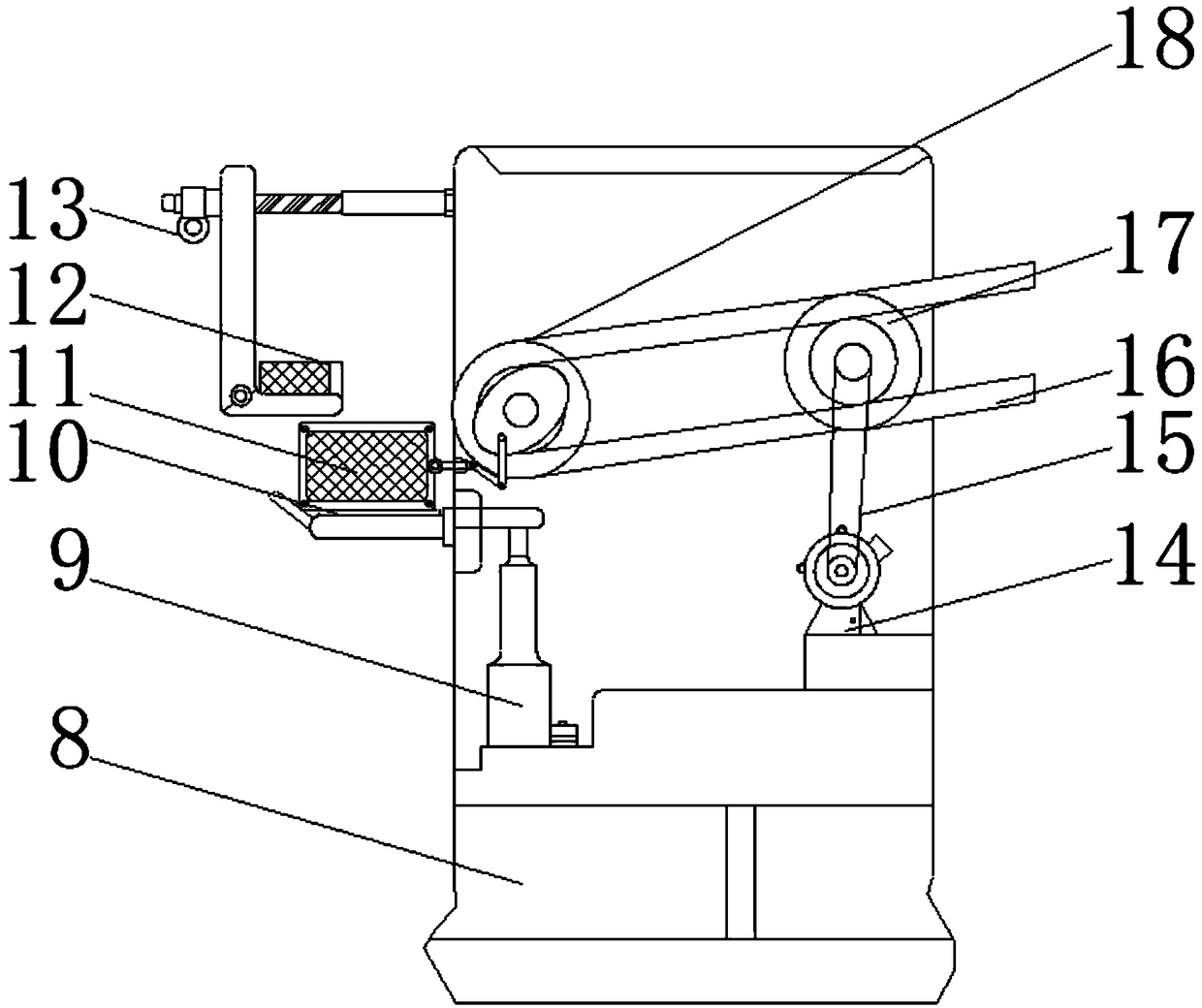
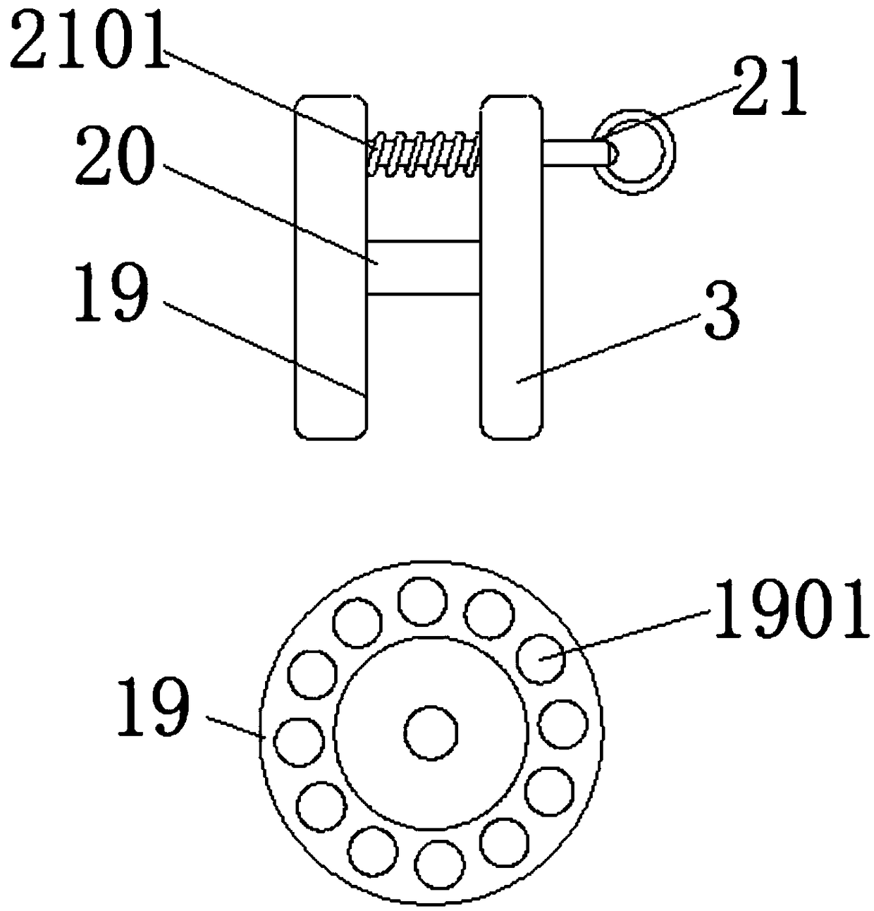
The invention discloses an automatic cutting and receiving auxiliary device for labels. The automatic cutting and receiving auxiliary device comprises a main shell, a movable frame and a hanging plate; a thread barrel is welded to one side surface of the main shell; a screw rod is arranged in the thread barrel by a thread body; the bottom end of the hanging plate is provided with a baffle plate bya rotating shaft; a limiting chute is formed in the top end of the movable frame; an electric pushing rod is fixedly arranged in the main shell; a power motor is fixedly arranged in the main shell atone side of the electric pushing rod; a drive roller is arranged in the main shell above the power motor by a bearing; a driven roller is arranged in the main shell at one side of the drive roller bya bearing; and the surface of the driven roller and the surface of the drive roller are sleeved and connected with a conveying belt. According to the automatic cutting and receiving auxiliary devicedisclosed by the invention, by installing a series of structures, when being received by the device, the cut labels can be helped to evenly fall into a receiving component; shutdown operation can be avoided, which is convenient for continuous receiving to be realized.

Description

technical field [0001] The invention relates to the technical field of label production, in particular to an auxiliary device for automatic label cutting and receiving. Background technique [0002] Labels for electronic products are printed materials used to identify the relevant instructions of electronic products, and most of them are self-adhesive on the back. There is also a self-adhesive label. In the production and processing of electronic products, a large number of them are often used Labels, in order to ensure large-scale production efficiency, often use automated equipment to print labels, and the cost of forming is often that multiple labels are glued together, in the shape of strips or blocks, and some cutting equipment is required to cut them. After cutting, the material is often collected manually, and the efficiency of the material is not good. Some auxiliary devices are needed, but the structure of this type of auxiliary device is too simple, and specific op...

Claims


Application Information

Patent Timeline
IPC IPC(8): B26D7/32
CPCB26D7/32B26D2007/322Y02W30/62
Inventor 景波
Owner 苏州利通印刷有限公司
Learn More