Spare power automatic switching device control system for electric power

A technology of device control and self-switching, which is applied in the direction of circuit devices, electrical components, emergency power supply arrangements, etc., can solve problems such as inconvenient practical use, generation of waste products, production stoppage, etc., and achieve the effect of being convenient for practical use

Inactive Publication Date: 2021-01-08
南京易联科信息技术有限公司
View PDF0 Cites 0 Cited by
  • Summary
  • Abstract
  • Description
  • Claims
  • Application Information

AI Technical Summary

Problems solved by technology

[0002] Standby self-switching device is the abbreviation of the device for automatically putting into use the backup power supply. The interruption of power supply will cause production to stop, life chaos, and the installation will endanger the safety of people and equipment, resulting in very serious consequences. The first level of load: the power supply of this level of load is interrupted will cause personal accident
If the equipment is damaged, waste products will be produced, the production order cannot be restored for a long time, and people's lives will be chaotic, etc.; the second level of load: the interruption of power supply to this level of load will cause a large reduction in production, which will affect people's lives, etc.; the third level of load: all Loads that do not belong to the first and second levels, such as the subsidiary workshops of factories, small towns, etc. In addition, there are special and important loads with a very small number or a short duration that require absolutely reliable uninterrupted power supply. Ensure uninterrupted power supply; for the second-level load, if possible, uninterrupted power supply should also be guaranteed, and the backup self-switching method is used to greatly speed up the recovery of power supply: if the backup power supply has power, the power supply can be restored within a few seconds; It takes at least a few minutes to use manual power transmission after the power is turned off. The existing backup automatic switching device will automatically activate after power failure and enter the working mode. At this time, workers need to check it and modify the value. There are certain defects in the self-injection device, which is not convenient for practical use

Method used


Image

  • Spare power automatic switching device control system for electric power
  • Spare power automatic switching device control system for electric power
  • Spare power automatic switching device control system for electric power

Examples


Embodiment Construction

[0023] The present invention will be further described below in conjunction with the accompanying drawings, but the protection scope of the present invention is not limited to the following description.

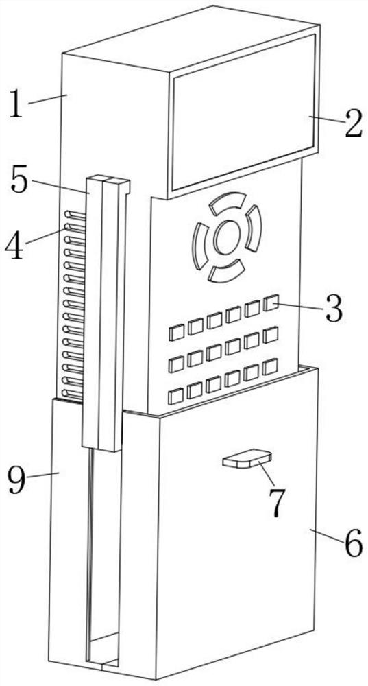
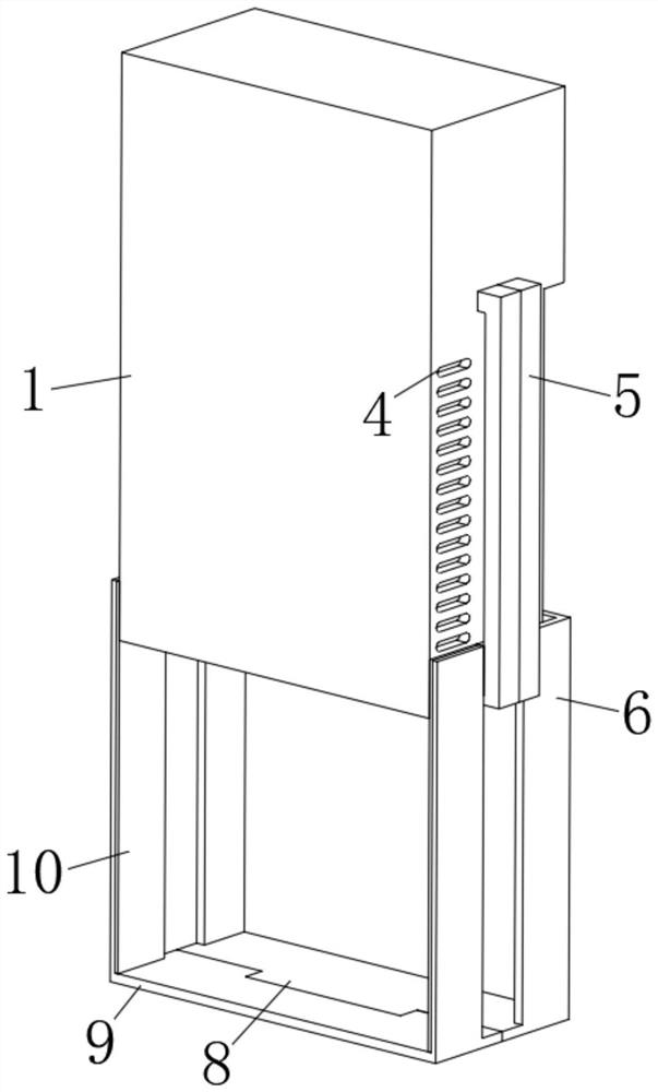
[0024] Such as Figure 1-6 As shown in the figure, a control system for self-injection device for electric power standby, it includes a device main body 1, a display screen 2 is arranged on one side of the device main body 1, a button 3 is arranged on one side of the device main body 1, and two sides of the device main body 1 are provided with There is a heat sink 4, and one side of the main body 1 of the device is fixedly connected with a sliding mechanism 5, and the number of the sliding mechanism 5 is two groups;

[0025] One side of the device main body 1 is movably connected with a protective cover 6 through one of the sliding mechanisms 5, one side of the protective cover 6 is fixedly connected with a pull block 7, and one side of the protective cover 6 is fixedly conne...


PUM


Abstract

The invention relates to the technical field of spare power automatic switching devices, in particular to an electric power spare power automatic switching device control system which comprises a device body, a display screen is arranged at one side of the device body, a button is arranged at one side of the device body, heat dissipation grooves are formed in the two sides of the device body, andtwo sliding mechanisms are fixedly connected to one side of the device body . The system has the advantages that the sliding mechanisms are arranged, one side of the device body is movably connected with the protective cover through one sliding mechanism, one side of the device body is movably connected with the sealing block through the other sliding mechanism, when the device is used, a protective cover is pulled down, the button is used for adjustment, and the protective cover is closed after adjustment is completed; after the device main body enters a working state, the sealing block is pulled down, the heat dissipation groove is exposed, heat is discharged, and when the device main body does not work, the sealing block seals the heat dissipation groove, so that dust is prevented frominvading the device main body.

Description

technical field [0001] The invention relates to the technical field of standby automatic switching devices, in particular to a control system for electric power standby automatic switching devices. Background technique [0002] Standby self-switching device is the abbreviation of the device for automatically putting into use the backup power supply. The interruption of power supply will cause production to stop, life chaos, and the installation will endanger the safety of people and equipment, resulting in very serious consequences. The first level of load: the power supply of this level of load is interrupted Personal accident will result. If the equipment is damaged, waste products will be produced, the production order cannot be restored for a long time, and people's lives will be chaotic, etc.; the second level of load: the interruption of power supply to this level of load will cause a large reduction in production, which will affect people's lives, etc.; the third leve...

Claims


Application Information

Patent Timeline
IPC IPC(8): H02J9/06
CPCH02J9/06
Inventor 蔡义琴杨兴留
Owner 南京易联科信息技术有限公司
Why Eureka
Try Eureka