Electric high stacking power vehicle capable of being easily controlled

A power car and electric technology, applied in the direction of lifting devices, etc., can solve problems such as undesigned pedals, casualties, and difficulty in steering when stacking high power cars

Active Publication Date: 2018-11-16
ZHEJIANG OCEAN UNIV
View PDF9 Cites 3 Cited by
  • Summary
  • Abstract
  • Description
  • Claims
  • Application Information

AI Technical Summary

Problems solved by technology

[0003] On the one hand, most of the existing electric stackers do not have pedals. During the driving process of the stacker, the workers walk behind the stacker, which brings certain difficulties to the workers to operate the stacker.
[0004] On the other hand, the control panel of the existing high-powered car is generally designed at the tail of the high-powered car. Since the worker n

Method used


Image

  • Electric high stacking power vehicle capable of being easily controlled
  • Electric high stacking power vehicle capable of being easily controlled
  • Electric high stacking power vehicle capable of being easily controlled

Examples


Embodiment 1

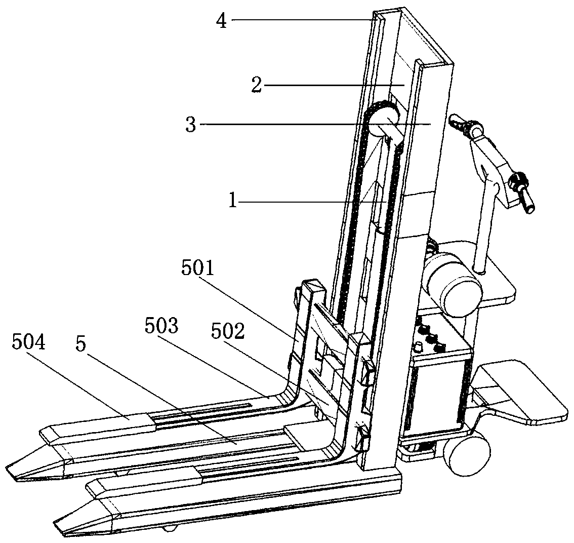
[0099] An electric stacking power vehicle that is easy to control, the electric stacking power vehicle includes a hydraulic lifting device 1, a back plate 2, a side plate 3, a guide rail groove 4, a fork assembly 5, a traveling device 30, a front wheel 31, and a front foot 32; There are two side plates 3, which are fixed on both sides of the back plate 2, and the guide rail groove 4 is fixed on the side plate 3; the front legs 32 are two, arranged in parallel, and connected to the lower ends of the side plates 3 respectively, and the front wheels 31 are connected to the front legs 32 away from the the lower side of one end of the side plate 3;

[0100] The hydraulic lifting device 1 includes a chain connection block 6, a chain 7, a pulley 8, a hydraulic rod outer tube 9, a hydraulic rod inner tube 10, a pulley shaft 34 arranged on the inner side of the guide rail groove 4, and also includes an oil cylinder 11, an oil pipe 12, and a motor 13; The motor 13 is arranged on the oil...

Embodiment 2

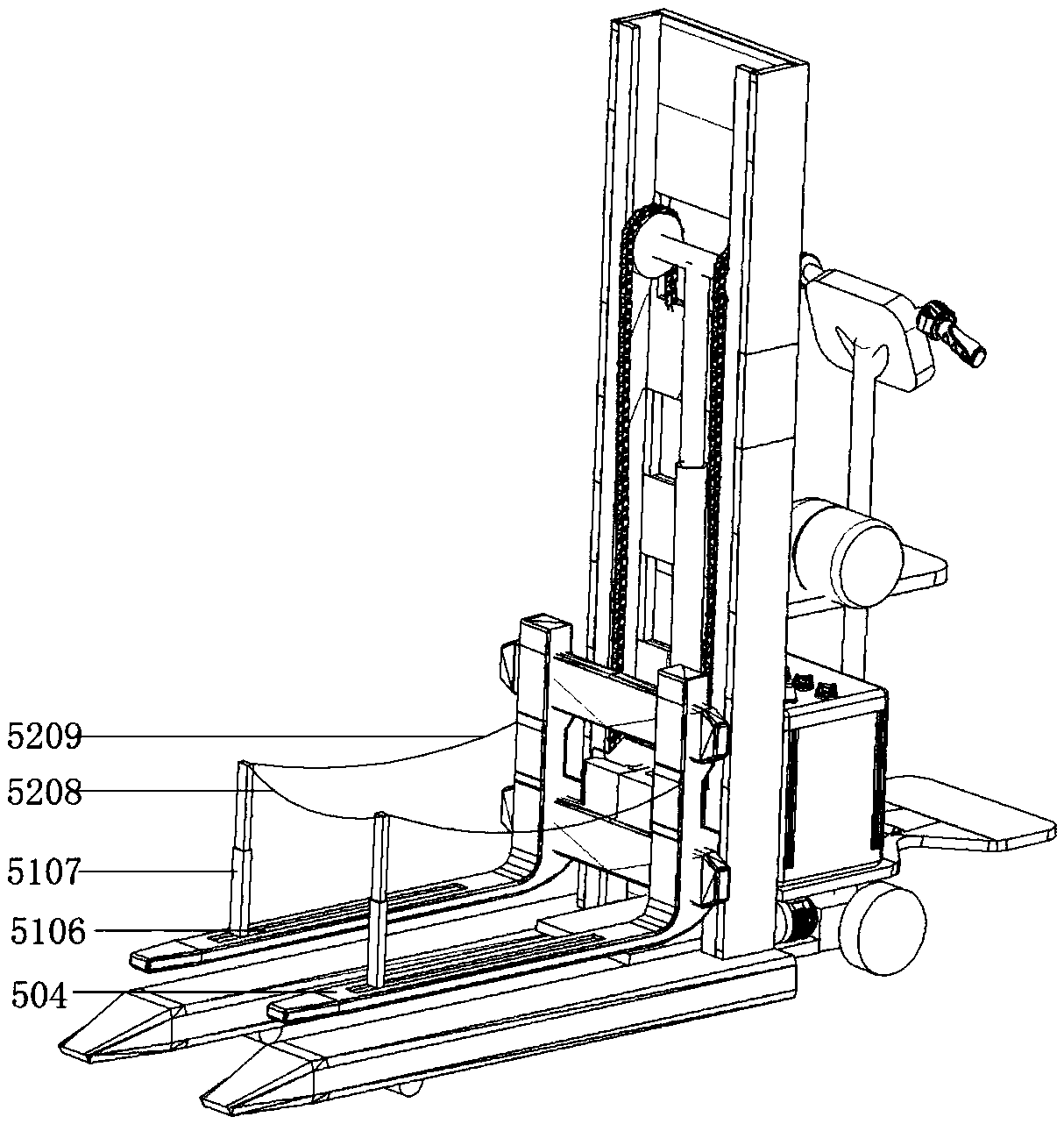
[0116] The fork assembly 5 of the stacker in this embodiment also includes a second power switch 5104, a second controller 5111, a second sliding assembly, a connecting assembly, and a fixed rod group 5107. The second power switch 5104 is arranged outside the bracket 501, extending The arm 504 is an open tubular structure with a fixed rod chute 5106 on the upper part, and the second controller 5111, the second sliding assembly, the connecting assembly, and the fixed rod group 5107 are arranged inside the tubular structure of the extension arm 504;

[0117]The second controller 5111 is arranged at one end of the extension arm 504 close to the beam 502, the second sliding assembly is arranged at the other end of the extension arm 504, the connecting assembly is arranged on the second sliding assembly, and the fixed rod group 5107 is connected with the second sliding assembly through the connecting assembly. The components are hinged, and the fixed rod group 5107 can be turned inw...

Embodiment 3

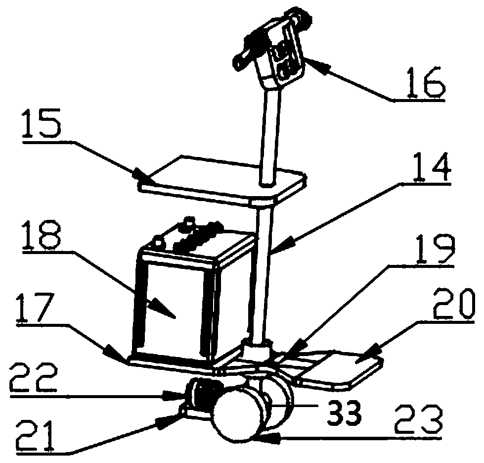
[0129] In this embodiment, the push-up cart is provided with a folding seat 40, a main folding area 36, ​​a substrate installation strip 37, a substrate 38, and a substrate chute 39;

[0130] There are two substrate mounting strips 37, which are fixed on both sides of the bottom of the traveling device 30 in parallel; the substrate chute 39 is arranged inside the substrate mounting strip 37; the substrate 38 is installed in the substrate chute 39, and can slide back and forth along the substrate chute 39;

[0131] The main folding area 36 is arranged on the surface of the base plate 38; the folding seat 40 includes a seat plate 4011, a back plate 4012, a U-shaped support rod placement groove 4015, a seat plate support rod placement groove 4016, a U-shaped support rod 4017, and a U-shaped support rod support groove 4018, upright post 4019, support rod adjustment hole 4020, locking bolt 4021, backing plate chute 4022, backing plate adjustment hole 4023, post fixing hinge 4024, se...


PUM


Abstract

The invention provides an electric high stacking power vehicle capable of being easily controlled. A pedal is arranged on the rear side of the electric high stacking power vehicle, and a control panelis arranged in the middle of a direction turning handle, so that relative still between a worker and the high stacking power vehicle can be guaranteed, the operation difficulty is reduced, the physical strength of the worker is saved, and the working efficiency is improved; on the other hand, the direction turning handle is held by two hands of the worker during the driving process of the high stacking power vehicle so that the high stacking power vehicle can be conveniently controlled to turning the direction; and when an emergency situation occurs, the buttons on the control panel can be operated in time to realize acceleration and deceleration and the lifting of a fork, the problem that the control panel cannot be controlled due to the fact that the distance of the control panel is toofar is avoided, so that the operation difficulty of the worker is lowered, the worker is enabled to have sufficient reaction time, the probability of accidents can be effectively reduced, and the working efficiency is improved.

Description

technical field [0001] The invention relates to the field of mechanical equipment, in particular to a controllable electric stacker power vehicle. Background technique [0002] Stacking power trucks are widely used in factory workshops, warehouses, distribution centers and distribution centers, ports, stations, airports, freight yards, etc., and can enter cabins, carriages and containers for loading, unloading and handling of palletized goods. [0003] On the one hand, most of the existing electric stackers do not have pedals. During the driving process of the stacker, the workers walk behind the stacker, which brings certain difficulties to the workers to operate the stacker. . [0004] On the other hand, the control panel of the existing high-powered car is generally designed at the tail of the high-powered car. Since the worker needs to hold the steering handle with both hands, it is necessary to control the forward, backward, driving speed, brakes and cargo of the high-...

Claims


Application Information

Patent Timeline
IPC IPC(8): B66F9/22B66F9/075B66F9/06B66F9/12
CPCB66F9/06B66F9/07572B66F9/0759B66F9/12B66F9/22
Inventor 盛露峰陈林王世来王涛王化明吕俊
Owner ZHEJIANG OCEAN UNIV
Why Eureka
Try Eureka