Novel packer release joint

A packer, a new type of technology, applied in the direction of wellbore/well components, earthwork drilling and production, etc., can solve the problems of difficulty in dropping hands, very high operation requirements, affecting the diameter of the pipe, etc., to achieve small rotational torque, reliable insertion, The effect of ensuring the sealing of tools

Pending Publication Date: 2018-11-16
CHENGDU WEST PETROLEUM EQUIP +1
View PDF0 Cites 1 Cited by
  • Summary
  • Abstract
  • Description
  • Claims
  • Application Information

AI Technical Summary

Problems solved by technology

When the mechanical operation is lost, it is often necessary to find the neutral point of the pipe string for undercutting. In some deep wells and highly deviated wells, the requirements for on-site operations are very high, especially for pipes that have been in the well for a long time, and it is difficult to lose hands ; Hydraulic throws often need to drop the ball to suppress the pressure, but the ball seat will affect the inner diameter of the pipe

Method used


Image

  • Novel packer release joint
  • Novel packer release joint
  • Novel packer release joint

Examples


specific Embodiment 1

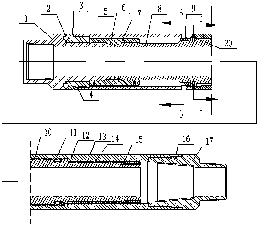
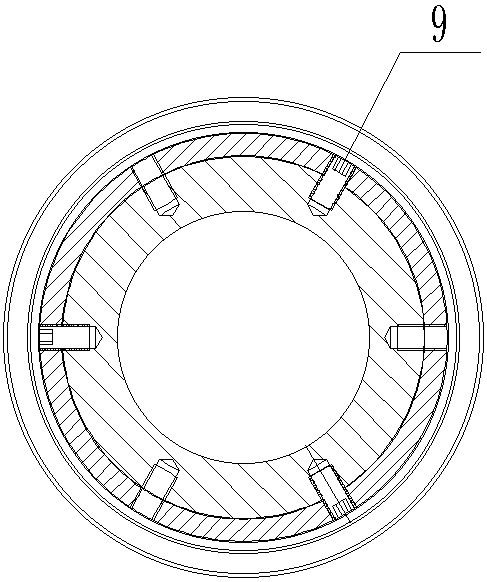
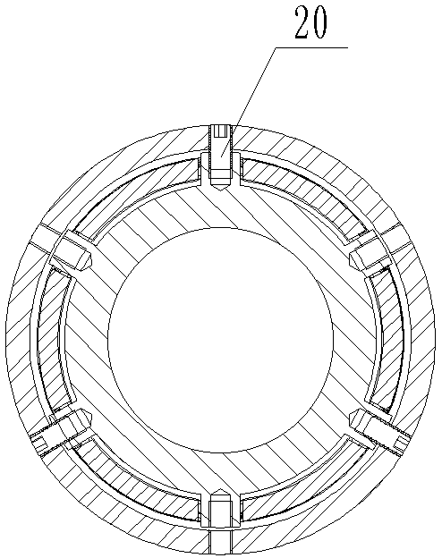
[0037] Specific embodiment 1: as figure 1 As shown, before entering the well, connect the drop-off joint and the packer on the ground. The packer is a mechanical seat packer. After installing the shear nail I20, the mandrel 8 and the jaw sleeve 11 are relatively fixed. , send the drop-off joint and the packer down, and then set the packer in place, and rotate the pipe string. Due to the action of the shear nail I20, the mandrel 8 will be together with the jaw sleeve 11 and the elastic jaw 10. Rotate, when the number of turns of the rotating seat packer reaches the required number of turns, slowly press down to make the pipe string under pressure. Stuck, if the packer slip seat is stable, continue to press down the pipe string, the shear nail I20 will be cut off, and the seat seal packer will be closed at the same time. The lower end surface of 5 is in contact with the upper end surface of the claw sleeve 11, the upper end surface of the outer sleeve 5 is connected with the be...

specific Embodiment 2

[0038] Specific embodiment 2: as Figure 4 As shown, before entering the well, connect the drop-off joint with the packer on the ground. The packer is a hydraulic seated packer. To seal the packer, press down to make the pipe string under pressure. At this time, the lower end surface of the outer sleeve 5 and the upper end surface of the claw sleeve 11 fit together to prevent debris in the well from entering the threaded joint. Press down the pipe string so that the lower end surface of the outer sleeve 5 is in contact with the upper end surface of the claw sleeve 11, and the upper end surface of the outer sleeve 5 is connected with the bearing cover 3, and the pipe string is rotated forward, and the elastic claw 10 spirals up until all the threads are unscrewed. Realize throwing away. During the process of pressing down and rotating the pipe string, the pressure always acts on the steel ball 2 and the bearing cover 3. At this time, the anchoring claw is not subject to pressur...


PUM


Abstract

The invention discloses a novel packer release joint comprising an upper joint body, a bearing cover, a middle sleeve, an outer sleeve, a central spindle, a lower joint body, a back-inserting shear pin, a shearing pin I, an elastic clamping claw, a clamping claw sleeve and a tail sleeve; the lower end of the upper joint body is connected with the upper end of the central spindle through the middlesleeve, the upper end of the middle sleeve makes contact with the lower end of the bearing cover, the exterior of the lower end of the central spindle is sleeved with the tail sleeve, the exterior ofthe upper end of the lower joint body is sleeved with the clamping claw sleeve, the exterior of a stepped shaft of the upper joint body is sleeved with the bearing cover, and a steel ball is arrangedat the junction of the upper joint body and the bearing cover; and the exterior of the central spindle is sleeved with the elastic clamping claw, the exterior of the elastic clamping claw is sleevedwith the clamping claw sleeve, the clamping claw sleeve is connected with the central spindle through the shear pin I, the elastic clamping claw is connected with the central spindle through the back-inserting shear pin, and the exterior of the middle sleeve is sleeved with the outer sleeve. The novel packer release joint has the beneficial effects that the neutralization point does not need to befound, a release can be easily buckled reversely only by downwards pressing a certain tonnage and forwards rotating a pipe column, and the novel packer release joint can be used for a mechanical packer and a hydraulic packer.

Description

technical field [0001] The invention relates to the field of oil production equipment, in particular to a novel packer drop-off joint. Background technique [0002] In the process of oil production, the packer is a device fixed on the pipe string, and the annulus of the oil sleeve is sealed through the setting of the packer to realize stratification. [0003] According to the on-site process requirements, generally a drop joint is required on the upper part of the packer, also known as insertion seal, anchor seal, etc. , the drop-off joint is separated from the packer, and secondly, after the drop-off is successful, the tubing string needs to be replaced and reinserted. The drop-off methods are generally divided into mechanical and hydraulic types. When the mechanical operation is lost, it is often necessary to find the neutral point of the pipe string for undercutting. In some deep wells and highly deviated wells, the requirements for on-site operations are very high, espe...

Claims


Application Information

Patent Timeline
Patent Type & Authority Applications(China)
IPC IPC(8): E21B23/06
CPCE21B23/06
Inventor 沈鹏胡永昌李仁华蒋化林
Owner CHENGDU WEST PETROLEUM EQUIP
Why Eureka
Try Eureka