
Double-spring pressure reducing valve

A pressure reducing valve and double spring technology, applied in the field of double spring pressure reducing valve, can solve the problems of small elasticity, troublesome adjustment, limited sealing effect, etc., and achieve the effect of improving elasticity, increasing range and good sealing effect

Inactive Publication Date: 2018-11-16
DONGGUAN TIANHE ELECTROMECHANICAL DEV CO LTD
View PDF0 Cites 0 Cited by
  • Summary
  • Abstract
  • Description
  • Claims
  • Application Information

AI Technical Summary

Problems solved by technology

[0002] The existing pressure reducing valve generally adopts the sleeve spring in the connecting sleeve body formed on the top surface of the middle part of the valve body, and presses against the valve stem on the top surface of the valve core through the spring, and the diaphragm is fixed on the valve body. On the top surface of the rod, through the downward elastic force of the spring, the elastic force of the diaphragm and the pressure of the circulating water flow, the height adjustment of the valve core is realized, and the water flow is realized. The adjustment of the single spring is limited in its elastic force adjustment, and The elasticity of the diaphragm is generally smaller than that of the spring, and its adjustment is troublesome, and the valve core generally adopts a plate with a circular cross section, and its sealing effect is limited.

Method used


Image

  • Double-spring pressure reducing valve

Examples


Embodiment Construction

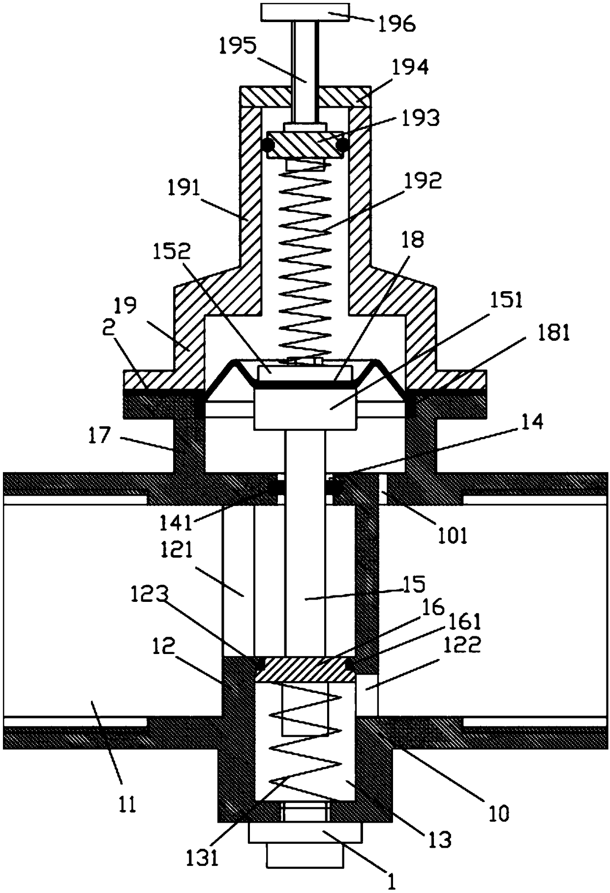
[0016] Examples, see e.g. figure 1 As shown, a double spring pressure reducing valve includes a valve body 10, the left end and the right end of the valve body 10 are formed with a flow connecting pipe part 11, and the middle part of the valve body 10 is formed with a cylindrical sleeve body 12, and the cylindrical sleeve body 12 The top and bottom ends of the valve body 10 are formed on the top and bottom surfaces of the valve body 10. The upper left side of the cylindrical sleeve body 12 has an upper through groove 121, and the lower right side of the cylindrical sleeve body 12 is formed with a lower through groove 122. The inner bottom surface of the valve body 10 at the bottom surface of the sleeve body 12 is formed with a cylindrical extension sleeve body part 13 extending downward, and the inner top surface of the valve body 10 at the top of the cylindrical sleeve body 12 is formed with a through hole 14, and the vertical rod 15 is inserted into the through hole 14, the ...


PUM


Abstract

The invention discloses a double-spring pressure reducing valve. The double-spring pressure reducing valve comprises a valve body, the left end and the right end of the valve body are each provided with a circulating connecting pipe portion, and the middle of the valve body is provided with a cylindrical sleeve body; the top end and the bottom end of the cylindrical sleeve body are molded on the top face and the bottom face of the interior of the valve body; the upper portion of the left side of the cylindrical sleeve body is provided with an upper through groove; the lower portion of the right side of the cylindrical sleeve body is provided with a lower through groove; a cylindrical extending sleeve body portion extending downwards is arranged on the bottom face of the interior of the portion, on the bottom face of the cylindrical sleeve body, of the valve body; and a through hole is formed in the top face of the interior of the portion, at the top end of the cylindrical sleeve body,of the valve body, a vertical rod is inserted into the through hole, and the lower portion of the vertical rod is inserted into the cylindrical sleeve body. According to the double-spring pressure reducing valve, the double-spring effect of an adjusting spring and a lower buffering spring is adopted, the elastic force is increased, and the pressure adjusting range is widened; meanwhile, a valve element shaped like a circular truncated cone is adopted, and therefore the sealing effect is good; and in addition, the edge of an elastic membrane is provided with an annular convex portion extendingupwards, and therefore the elastic force of the elastic membrane is increased.

Description

Technical field: [0001] The invention relates to the technical field of valves, in particular to a double-spring decompression valve. Background technique: [0002] The existing pressure reducing valve generally adopts the sleeve spring in the connecting sleeve body formed on the top surface of the middle part of the valve body, and presses against the valve stem on the top surface of the valve core through the spring, and the diaphragm is fixed on the valve body. On the top surface of the rod, through the downward elastic force of the spring, the elastic force of the diaphragm and the pressure of the circulating water flow, the height adjustment of the valve core is realized, and the water flow is realized. The adjustment of the single spring is limited in its elastic force adjustment, and The elastic force of the diaphragm is generally smaller than that of the spring, and its adjustment is troublesome, and the valve core generally adopts a plate body with a circular cross ...

Claims


Application Information

Patent Timeline
IPC IPC(8): F16K1/32F16K1/46F16K27/02F16K41/02F16K41/12
CPCF16K1/32F16K1/46F16K27/02F16K41/02F16K41/12
Inventor 胡惠娟
Owner DONGGUAN TIANHE ELECTROMECHANICAL DEV CO LTD
Learn More