High-pressure difference sleeve adjusting valve

A technology of sleeve regulating valve and high pressure difference, which is applied in the direction of lifting valve, valve details, valve device, etc., can solve the problems of loose closing of regulating valve, erosion, blowing damage of sealing surface, etc., and achieve the effect of avoiding blowing damage

Pending Publication Date: 2018-11-16
SICHUAN BINDA VALVE CO LTD +2
View PDF0 Cites 2 Cited by
  • Summary
  • Abstract
  • Description
  • Claims
  • Application Information

AI Technical Summary

Problems solved by technology

However, simply using this structure to reduce pressure, in a high-pressure environment, when the valve core is opening and closing, the flow channel area is extremely small, the medium flow rate is high and the pressure drops sharply, and the valve sealing surface is still vulnerable to high-speed medium. Fluid scouring and erosion phenomenon will result in blowing damage to the sealing surface. In severe cases, the regulating valve will not be closed tightly, internal leakage will occur, and it will also cause problems such as scouring wear and loud noise.

Method used


Image

  • High-pressure difference sleeve adjusting valve
  • High-pressure difference sleeve adjusting valve
  • High-pressure difference sleeve adjusting valve

Examples


Embodiment 1

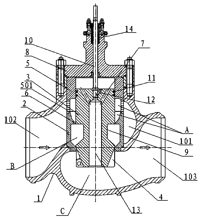
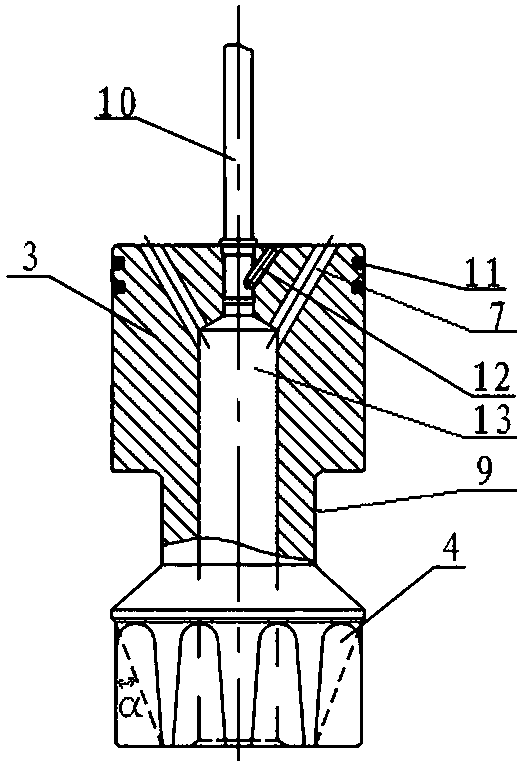
[0024] see Figure 1 to Figure 3 As shown: the present invention is a high-pressure differential sleeve regulating valve, including a valve body 1, a valve cover 8, and a valve trim arranged in the valve body 1 and the valve cover 8, and the valve trim further includes a valve cage 5 , a valve seat 2, a valve stem 10, and a valve core 3, the valve core 3 is fixedly connected to the lower end of the valve stem 10. In this embodiment, the top of the valve cavity 101 of the valve body 1 is sealed by the valve cover 8, and the valve cover 8 is provided with an axial through hole 13 of the valve stem 10, and one end of the valve stem 10 passes through the The axial through hole 13 of the bonnet 8 extends into the valve chamber 101 in the valve body 1, and is screwed with the internal thread at the top of the axial through hole 13 opened in the center of the valve core 3, and the locking screw 12 Fixed and locked; the valve stem 10 is axially arranged in the valve chamber 101 throu...

Embodiment 2

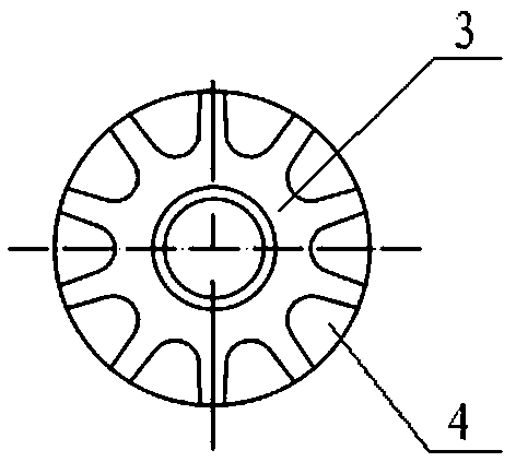
[0032] see Figure 4 , Figure 5 The other structure of this embodiment 2 is the same as that of embodiment 1, the difference is that the cross-sectional shape of the longitudinal flow regulating groove 4 of the valve core 3 is rectangular, and the depth of the longitudinal flow regulating groove 4 is monotonously deepened from top to bottom, and vertically The width of the flow regulating groove remains constant from top to bottom. It is easy to process.

Embodiment 3

[0034] Other structures of the third embodiment are the same as those of the first embodiment, except that: the notch of the adjusting groove is provided with an everted arc-shaped chamfer. When the spool opens and closes, it increases the area of ​​the flow passage, reduces the erosion and erosion of high-speed fluid, and realizes the smooth transition of the spool opening and closing.


PUM


Abstract

The invention discloses a high-pressure difference sleeve adjusting valve. The high-pressure difference sleeve adjusting valve comprises a valve body, a valve cover and a valve inner piece which is arranged in the valve body and the valve cover. The valve inner piece further comprises a valve cage, a valve seat, a valve rod and a valve element. The valve element is fixedly connected with the lowerend of the valve rod. The valve cage and the valve seat are overlapped up and down and are of a sleeve structure relative to the valve element. A first medium pressure reducing buffer space is reserved between the valve cage and the upper segment of the valve element, a second medium pressure reducing buffer space is reserved between the valve seat and the lower segment of the valve element, andthe three-stage pressure reducing adjusting valve is formed with a third medium pressure reducing buffer space. According to the high-pressure difference sleeve adjusting valve, by means of the firstmedium pressure reducing buffer space, the second medium pressure reducing buffer space and the third medium pressure reducing buffer space, multi-stage pressure reducing is achieved, the phenomenon that the sealing face of the valve is prone to being scoured by high-speed medium fluid and erosion is caused is eliminated, and the problems that the sealing face is blown damage, inner leaking and erosive abrasion are caused, and the noise is large and other problems are avoided.

Description

technical field [0001] The invention relates to the field of valves, in particular to a high pressure difference sleeve regulating valve. Background technique [0002] The high pressure differential sleeve regulating valve is mainly used on high temperature and high pressure straight stroke valves to regulate and reduce pressure. The pressure-reducing structure inside directly determines the pressure-reducing effect of the high-pressure differential sleeve regulating valve. At present, most of the traditional high-pressure differential sleeve regulating valves have multiple flow holes on the sleeve (cage), through which the medium flows. After the hole, the pressure is reduced and buffered in the buffer space between the sleeve (cage) and the valve core to achieve the effect of reducing the pressure. However, simply using this structure to reduce pressure, in a high-pressure environment, when the valve core is opening and closing, the flow channel area is extremely small, t...

Claims


Application Information

Patent Timeline
Patent Type & Authority Applications(China)
IPC IPC(8): F16K47/04F16K1/36F16K1/00F16K1/46
CPCF16K47/04F16K1/00F16K1/36F16K1/46
Inventor 王谦向卫东刘波向小林
Owner SICHUAN BINDA VALVE CO LTD
Why Eureka
Try Eureka