Method for detecting surface defects
A technology for defect detection and detection, which is applied in the direction of optical testing flaws/defects, etc., can solve problems such as prone to missed inspections, reduce the probability of missed inspections, and improve accuracy
- Summary
- Abstract
- Description
- Claims
- Application Information
AI Technical Summary
Problems solved by technology
Method used
Image

Examples
Embodiment 1
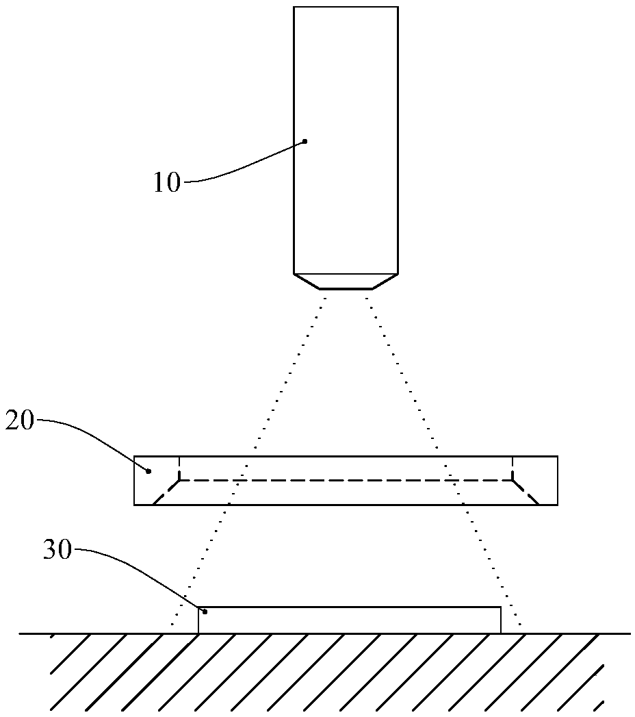
[0017] Such as figure 1 As shown, the hardware of the surface defect detection method in Embodiment 1 is a camera 10 , a light source 20 and a server (not shown), and the server controls the camera 10 and the light source 20 to work together. The camera head 10 adopts a CCD camera. The light source 20 is a ring light source, which can be evenly divided into 8 independent light sources that can emit light independently, and each independent light source occupies an azimuth of 45 degrees. During detection, each segment of independent light sources is controlled by the server to emit light, and the sequence of light emission starts from any segment of the independent light sources, and emits light sequentially counterclockwise or clockwise along the circumferential direction. The light source 20 is arranged between the camera 10 and the workpiece 30. The lens of the camera 10 faces down and passes through the hollow part of the light source 20 and points to the surface of the wo...
Embodiment 2
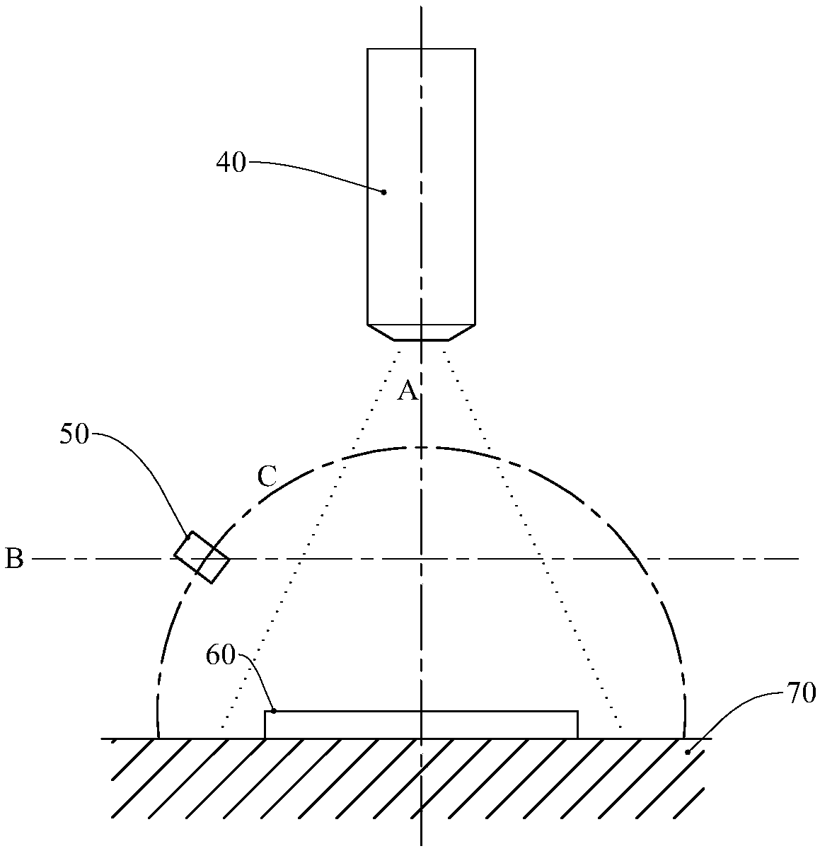
[0023] Such as figure 2 As shown, the hardware of the surface defect detection method in Embodiment 2 is a camera 40, a light source 50, a workbench 70 and a server (not shown), and the server controls the camera 40, light source 50 and workbench 70 to work together. The camera 40 adopts a CCD camera. The light source 50 is a point light source, such as a light bulb composed of LED lamp beads. The light source 50 is arranged between the camera 40 and the workpiece 60, but the light source 50 is not in the space formed by the connection line between the lens of the camera 40 and each point on the surface of the workpiece 60 to be detected, so as to prevent the light source 50 from blocking the surface of the workpiece 60 and causing surface area leakage. check. Different from the first embodiment, the light source 50 of the second embodiment is fixed, the camera 40 and the workpiece 60 can rotate synchronously (around the A axis), and the workpiece 60 is driven to rotate by ...
Embodiment 3
[0030] Such as figure 2 As shown, the hardware of the surface defect detection method in the third embodiment is a camera 40 , a light source 50 and a server (not shown), and the server controls the camera 40 and the light source 50 to work together. The camera 40 adopts a CCD camera. The light source 50 is a point light source, such as a light bulb composed of LED lamp beads. The light source 50 is arranged between the camera 40 and the workpiece 60, but the light source 50 is not in the space formed by the connection line between the lens of the camera 40 and each point on the surface of the workpiece 60 to be detected, so as to prevent the light source 50 from blocking the surface of the workpiece 60 and causing surface area leakage. check. Different from the second embodiment, the light source 50 of the third embodiment is rotatable, and the camera 40 and the workpiece 60 are fixed, and such a structure is relatively simpler than that of the second embodiment. In the t...
PUM
 Abstract
Description
Claims
Application Information
 - R&D
- Intellectual Property
- Life Sciences
- Materials
- Tech Scout
- Unparalleled Data Quality
- Higher Quality Content
- 60% Fewer Hallucinations
Browse by: Latest US Patents, China's latest patents, Technical Efficacy Thesaurus, Application Domain, Technology Topic, Popular Technical Reports.
© 2025 PatSnap. All rights reserved.Legal|Privacy policy|Modern Slavery Act Transparency Statement|Sitemap|About US| Contact US: help@patsnap.com