
Copying machine

Technology of a duplicating machine and body, applied in the field of duplicating machines

Inactive Publication Date: 2018-11-16
阜阳市金天数码科技有限公司
View PDF4 Cites 0 Cited by
  • Summary
  • Abstract
  • Description
  • Claims
  • Application Information

AI Technical Summary

Problems solved by technology

But, the copier commonly used at present can run into some problems in actual use

Method used

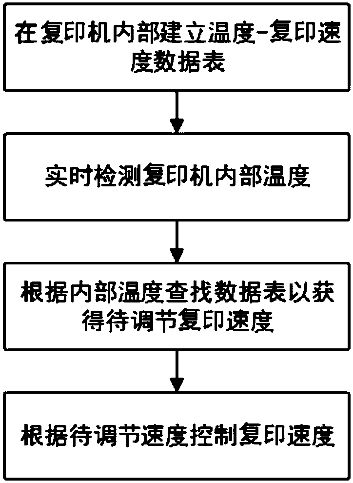

Image

  • Copying machine
  • Copying machine
  • Copying machine

Examples


Embodiment Construction

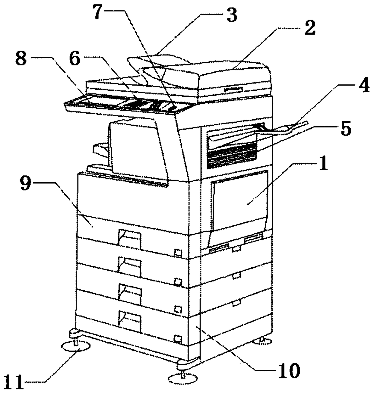
[0017] figure 1 A schematic diagram of a typical copier is shown. Such as figure 1 As shown, the structure of the copier can include a body 1, a light shield 2, a paper inlet 3, a paper outlet 4, a heat dissipation outlet 5, operation buttons 6, a main power switch 7, an operation display 8, a paper storage box 9, and a support frame 10, high foot bracket 11, light-shielding rubber 12. The shading plate 2 is arranged on the copier body 1, the paper inlet 3 is arranged on the copier body 1, the paper outlet 4 is arranged on the copier body 1, the heat dissipation port 5 is arranged on the copier body 1, and the operation buttons 6 are arranged on the copier body 1 Above, the operation display screen 8 is set on the copier body 1, the paper storage box 9 is set on the copier body 1, the main power switch 7 is set on the copier body 1, the support frame 10 is set on the copier body 1, and the light-shielding rubber 12 is set on On the light-shielding plate 2 , the high-leg sup...


PUM


Abstract

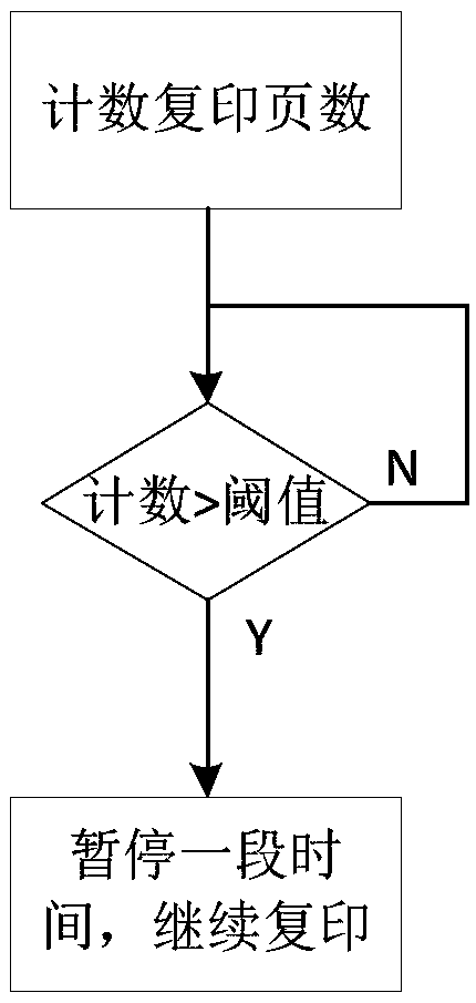
The invention relates to the field of copying machines, and discloses a copying machine. The copying machine comprises a ventilation device, a copying mechanism and a processor, wherein the ventilation device is positioned at the paper outlet of the copying machine and the ventilation device comprises an air outlet in at least one side of the inner sides of the paper outlet and an air supply device positioned inside a copying machine body; the copying mechanism is used for carrying out copying tasks; the processor is configured as follows: starting a copying task to start counting copied pages; judging whether a counting value reaches a threshold value or not; starting the ventilation device under the condition that the counting value reaches the threshold value.

Description

technical field [0001] The present invention relates to a copier. Background technique [0002] A copier refers to an electrostatic copier, which is a device that uses electrostatic technology to reproduce documents. The copier is an analog mode and can only copy documents truthfully. Digital copiers will make image storage, transmission, and editing and layout (image synthesis, information addition or deletion, local enlargement or reduction, error correction) possible. It can be connected with computers, word processors and other microprocessors through interfaces and become an important part of the regional network. Multifunctionality, colorization, cheapness, miniaturization, and high speed are still important development directions. However, the current commonly used duplicating machines can encounter some problems during actual use. Contents of the invention [0003] The object of the present invention is to provide a duplicating machine in order to overcome the ...

Claims


Application Information

Patent Timeline
IPC IPC(8): G03G21/20
CPCG03G21/20G03G21/206
Inventor 张丽影
Owner 阜阳市金天数码科技有限公司
Learn More