Microstrip series-fed array antenna, antenna area array and radio frequency front end of radar sensor
A technology for array antennas and microstrip antennas, applied in antennas, antenna arrays, antenna components, etc., can solve problems such as pattern beam deviation from the normal direction, excessive width of microstrip lines, and large variation range of matching section characteristic impedance , to achieve the effects of easy system integration, increased impedance bandwidth, and expanded application range
Pending Publication Date: 2018-11-16
湖南纳雷科技有限公司
View PDF0 Cites 16 Cited by
- Summary
- Abstract
- Description
- Claims
- Application Information
AI Technical Summary
Problems solved by technology
[0006] The first method refers to the document "Synthesis method of series-fed microstrip antennaarrays", which controls the radiation power of the array element by changing the width of the microstrip patch array element. However, this method has limitations in the design of traveling wave arrays. It requires The array element spacing deviates from the medium wavelength to meet the traveling wave condition, causing the pattern beam to deviate from the normal direction
[0007] The second method
Method used
View moreImage
Smart ImageViewing Examples


Examples
 PUM
| Property | Measurement | Unit |
|---|---|---|
| Thickness | aaaaa | aaaaa |
| Impedance bandwidth | aaaaa | aaaaa |
Abstract
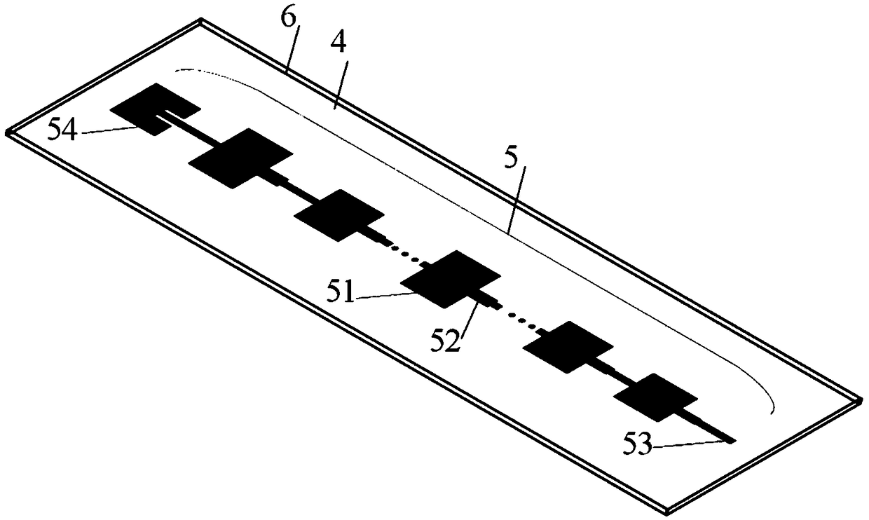
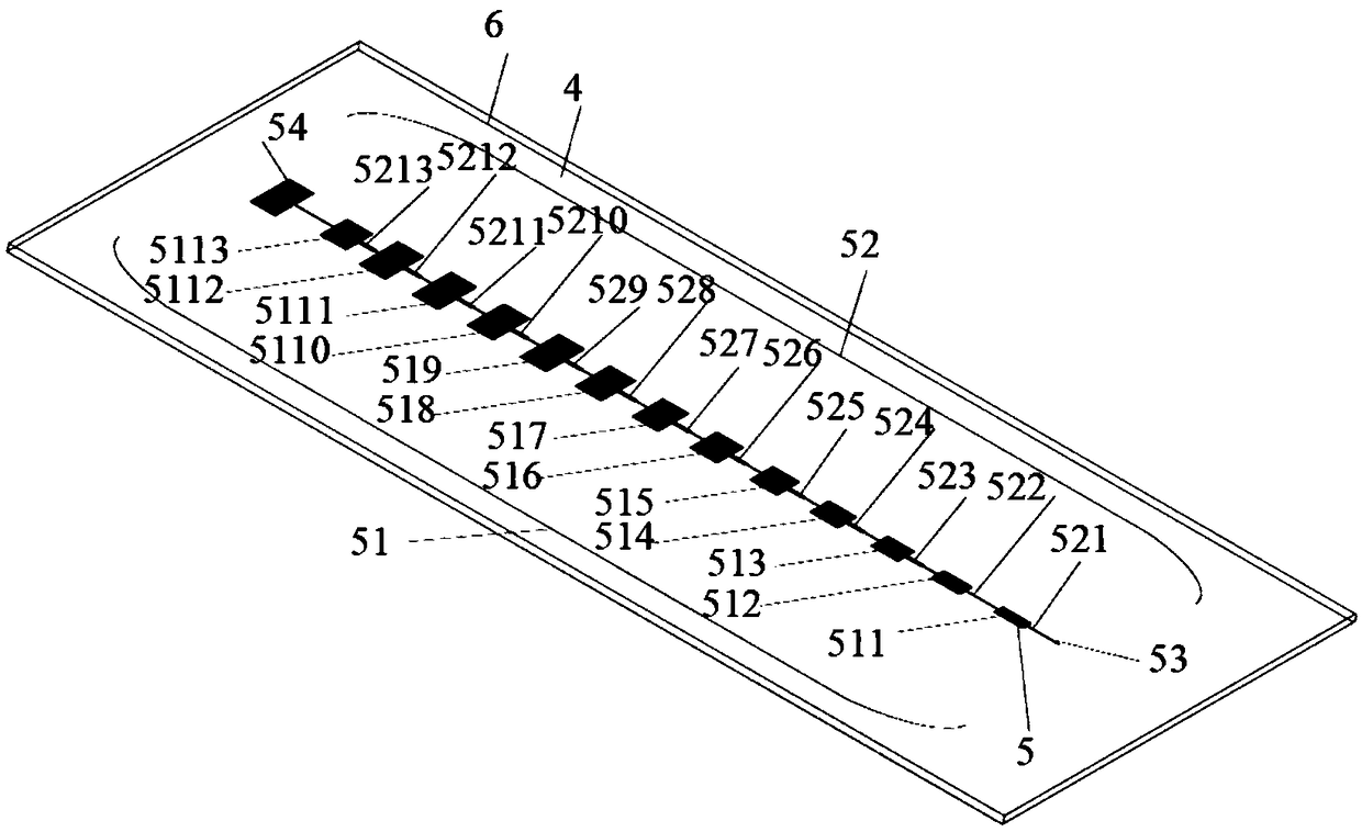
The invention relates to a microstrip series-fed array antenna, an antenna area array and a radio frequency front end of a radar sensor. The microstrip series-fed array antenna comprises a dielectricsubstrate, a microstrip structure formed by metal foil on the upper surface of the dielectric substrate and a ground formed by the metal foil on the lower surface of the dielectric substrate, whereinthe microstrip structure includes a plurality of microstrip antenna main radiation units, a plurality of matching branch units and a microstrip main feeder, and the plurality of microstrip antenna main radiation units form a horizontal-line-shaped array; the plurality of matching branch units are respectively arranged at the input ends of the plurality of microstrip antenna main radiation units and are arranged in a mode of being matched with the plurality of microstrip antenna main radiation units; and the plurality of microstrip antenna main radiation units and the plurality of matching branch units are connected through the microstrip main feeder. Both the antenna area array and the radio frequency front end of the radar sensor adopt the microstrip series-fed array antenna. The microstrip series-fed array antenna has the advantages of wide application range, ability of realizing the main beam pointing normal direction, ability of obtaining broadband impedance characteristics and thelike.
Description
technical field [0001] The invention mainly relates to the technical field of antennas, in particular to a microstrip series-fed array antenna, an antenna array and a radio frequency front end of a radar sensor. Background technique [0002] The microstrip antenna is an antenna formed by attaching a conductive sheet to a dielectric substrate with a conductive ground plane. It has the characteristics of small size, light weight, and easy integration. It can also be mass-produced through advanced printed circuit board technology. Very low cost. Due to the above advantages, microstrip antennas are widely used in the field of automotive radar. [0003] Vehicle-mounted radar systems usually require antennas such as antenna gain, sidelobe level, and specific beam shape. A single antenna has low gain and wide beam, so it is difficult to meet this requirement. Generally, microstrip arrays are used to achieve these indicators. [0004] The forms of microstrip array antenna mainly i...
Claims
Login to View More Application Information
Patent Timeline
 IPC IPC(8): H01Q1/38H01Q1/50H01Q21/00H01Q21/08H01Q1/32G01S7/02
CPCH01Q1/38G01S7/02H01Q1/3233H01Q1/50H01Q21/0075H01Q21/08
Inventor 易浩周坤明谭俊杰韩明华
Owner 湖南纳雷科技有限公司
Features
- R&D
- Intellectual Property
- Life Sciences
- Materials
- Tech Scout
- Unparalleled Data Quality
- Higher Quality Content
- 60% Fewer Hallucinations
Learn More Browse by: Latest US Patents, China's latest patents, Technical Efficacy Thesaurus, Application Domain, Technology Topic, Popular Technical Reports.
© 2025 PatSnap. All rights reserved.Legal|Privacy policy|Modern Slavery Act Transparency Statement|Sitemap|About US| Contact US: help@patsnap.com